P208
Antenna Rotator Systems
Need for Antenna Rotators
Better signals on any part of the spectrum are achievable where directional antennas are used. However, if the directional antenna is pointing away from the source, the signal rapidly becomes unusable. To resolve this issue the directional antenna has to be rotated towards the source. On this page we examine the devices which make antenna rotation possible.
Inherent risks of servicing
Antenna rotators are normally elevated, near the antennas and this places them in dangerous situations. Considerable care should be taken when installing, removing or servicing antenna rotator equipment. Only experienced persons with suitable safety equipment should attempt working at heights.
Specification Terms
Rotation Speed Larger antennas generally move more slowly. A typical full revolution of a rotator is 50-60 seconds. Smaller rotators with lighter loads may achieve full rotation in just 30 seconds.
Rotation torque This is usually specified in kg-cm or in the imperial inch-lbs. A medium duty rotator for HF beam antennas would be approximately 400 kg-cm (340in-lbs)
Thrust weight (vertical load) This figure describes the maximum weight of an antenna arrangement and rotating support pole. The thrust bearing race in a typical rotator would support up to 200kg. Heavier installations may have an additional thrust bearing mounted above the rotator to take some or all of the load from the motor unit.
Electric brake feature Basic rotators for light and medium loads have motors and gears which directly drive the output shaft. This is often sufficient, however if sufficient rotational load is placed upon the antenna assembly, strong winds can turn the rotator to a new direction, This effect is referred to as ‘windmilling’. Heavy duty rotators are often equipped with an electric brake feature which will keep the rotator position physically locked while the unit is in its passive state. The operator must press a Brake Release button to withdraw the lock whenever the antennas are being rotated to a new position. This is a particularly useful feature if the wind loading of the antenna is unbalanced.
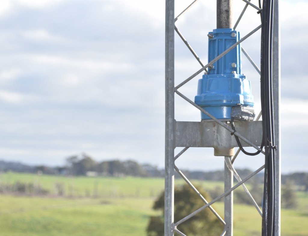
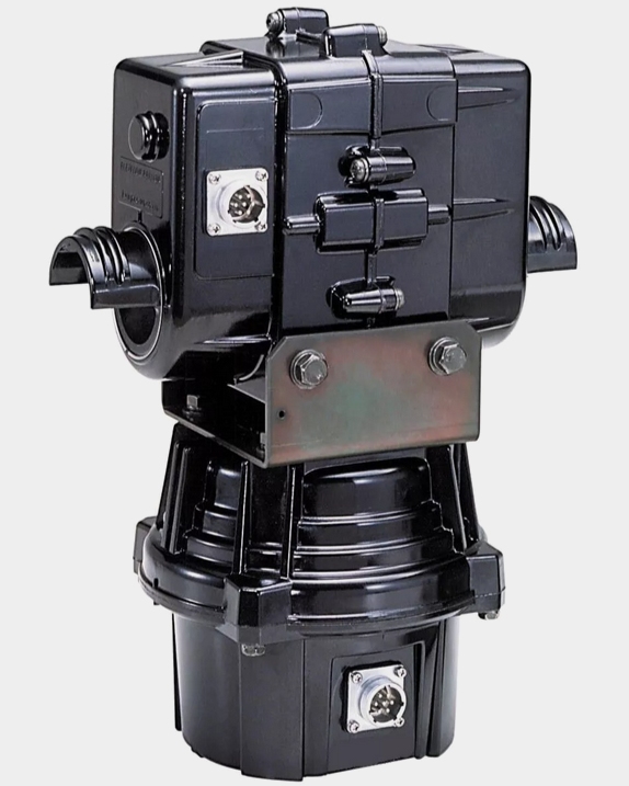
Inside an Antenna Rotator
Rotator units appear to be lumpy metal devices with the simple power to turn slowly. Inside they are quite sophisticated devices made up of gears, bearings and sensors.
Antenna rotators must deal with the worst of environmental elements of rain, wind loading, dust and layers of bird excrement and they must do it reliably many years, if not decades.
A freshly purchased secondhand rotator may appear clean on the inside, but don’t just install it. Take a little time to open it up, inspecting it and re-grease it if necessary.
(see the link to the refurbishment article at the end of this page)
Before installing a unit in a tower, get a short section of cable and hook it up to a control box on the bench and ensure that it has free movement over the full rotation. It is better to do a full functional test at ground level, rather than place it in the air and only then discover that there are problems.
Remember to set it North before powering down for an installation so that the antenna can be fixed in the Northerly direction when it is attached to the rotator.
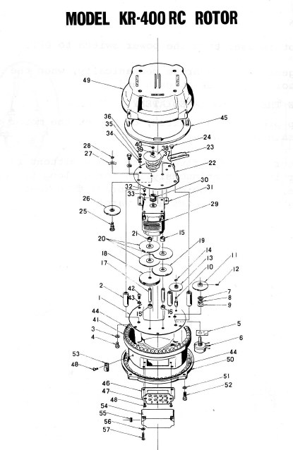
Rotators should always be disassembled from within a tray, as ball bearings may try escape from their working position as the case is separated.

Backstop position
Most rotators will not allow more than a single turn of antennas, clockwise or anticlockwise on the basis that to go further could damage coax cables that feed the movable antennas. At the end of a full turn a backstop internal to the rotator will prevent further rotation. In some rotators the backstop floats by a small amount permitting up to 380 degrees of rotation. Some thought should be applied to the antenna direction when at the centre of rotation. This is influenced by geography. For example in the Southern states of Australia, it makes sense for the centre position to be to the North because then only small rotational changes are needed to service between North West and North East. Conversely, if operating from say Darwin and commonly sought stations were Perth and Sydney, it would make sense for the centre of rotation to be South rather than having to rotate a ¾ turn to avoid the backstop and move between the two locations. Many rotators will come with alternate pointer scales so that the centre can be configured to be North or South.
Control units & wiring
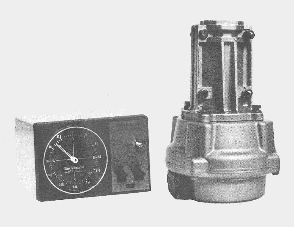
There is wide variety of complexity with rotator controls. Some use a potentiometer in the rotator to drive a needle on a panel meter graduated to different directions, such as the KR400 below. This just has two momentary buttons for clockwise (CW) and counter-clockwise (CCW) rotation. They use a basic 5 wire circuit. Three wires for the motor drive (Forward, Reverse, common) and two more wires for the position sensor. Cabling from the shack to the rotator can be achieved with inexpensive 5-core trailer cable.

Other control units use motor driven dials with a pointer that tries to match the current direction of the antenna using balanced circuits. It is common for sophisticated rotators to require up to eight wires between the shack and the antennas.

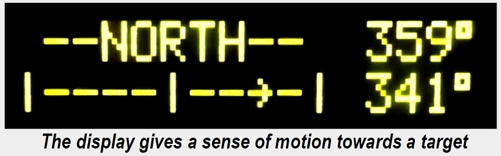
Some systems have a knob on the control box that is turned to a desired direction. The motor then drives the antenna until it matches the selected position on the control and rotation is halted. This method is quite friendly to use, allowing the operator to dial in a very specific angle. On this graphic display the top line shows the selected target and the lower line shows the antenna gradually rotating to the target.
The rotator cable
An important tip for running cable into a rotator is to ensure the cable approaches from the underside of the terminal strip, otherwise rain will follow the cable to the connection point and cause corrosion. In extreme cases it could allow rainwater to fill up the interior of the mechanism. As a precaution, cover up the terminal area with weatherproofing Butyl rubber or similar.

Azimuth Rotators
Sometimes direction alone is not enough. When tracking a satellite, it is necessary to have a vertical tilt of the antenna as well. This entails a second rotator for vertical tilt, or Azimuth adjustment. Most azimuth rotators are configured for antennas to attach to a pipe which passed entirely through the rotator. These work in conjunction with a regular horizontal rotator. This combination by Yaesu shows both mechanisms combined so that tracking antennas
Computer Controlled Rotation
Satellites move fast and it can be very difficult to maintain correct aim of a satellite antenna in to axis. This is something computers can do if there is a suitable interface between the rotator mechanism and a PC output. Yaesu designed a serial control protocol for rotators called GS-232A/B which has become the default interface method for this type of control.
Here is a You Tube video which shows this process in action
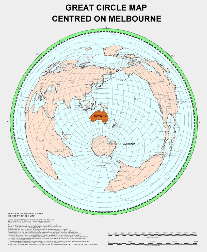
Setting direction by map (Mercator vs Great Circle)
Many Amateurs use the colourful Mercator projection maps in the shack as a guide for zones and international prefixes. These are useful, but are very poor at providing cues for rotating HF antennas to a preferred destination. In this image we can see a standard Mercator projection of the world

If we wanted to point the antenna from say Melbourne to Johannesburg in South Africa it would appear on the Mercator map that we should point the antenna due West. However, this is entirely wrong and due West would be closer to a London trajectory. With a Great Circle map the world has been distorted to give accurate beam headings from a specific location. In the map below we see that the correct direction for short-path to Johannesburg would be South West and Rio De Janeiro is almost due South.
Deterioration over time
Although rotators in service deserve a clean and grease re-pack every ten years, many of them never get this level of attention because of the difficulty of access involved. They should be re-packed with a marine grease, such as what is used on wheel bearings on boat trailers, because of the enhanced anti-corrosion characteristics. Where maintenance is not carried out, eventually the bearings will freeze and rust into position. Refurbishment is still possible but it takes more work to achieve. (Refer to the QTC article link at the end of this page)

Worn feedback sensor
A common failure mode is the wearing out of the position sensing potentiometer. Inside each rotator is a variable resistor where resistance is proportional to position. This provides feedback to the control box in the shack. Over time they wear dead spots in their resistive track. This is noticeable when rotating an antenna where the control needle flickers as rotation passes through certain positions. The only solution is to replace the pot with a new one. Sometimes these are conventional wire wound pots and are reasonably easy to obtain. Others use special pots without internal backstops and genuine parts are needed. (ref Duoro Services link below)

If the control box is a simple arrangement where the potentiometer drives a moving coil meter needle against a background panel, the effects of a worn pot are small. On smarter systems where the pot directly affects motor drive position, a worn pot can erratically force the antennas to odd directions.
Useful Links
Refurbishing an antenna rotator (Article in QTC magazine, August 2023 )
https://qtcmag.com/books/aryj/#p=22
Yaesu Rotator Control interface using GS232A (pdf download)
Rotator sales and spare parts in Australia Duoro Services
https://www.kur02.com.au/index.php?option=com_content&view=article&id=25&Itemid=111
