P265
Choosing the Best Coax Cable
Extracts from the QTC article Coax Comparisons, October 2020 by Ian Jackson VK3BUF
On this page we are not simply referencing feedline decibel loss tables and data sheets, we are going to physically test the differences between some common feedlines. Our aim is to discover just how important it really is to select the best, or at least adequate coax cable for the job and what some of these options are.
Performance Rules that affect every radio
While many factors do affect transmitter and receiver performance, we must remain aware of some universal constants that cannot be ignored. One such fundamental is the Inverse Square Law.
In this diagram, Square A has the same area as Square B. Also Square B is twice as distant from the point of origin as Square A.
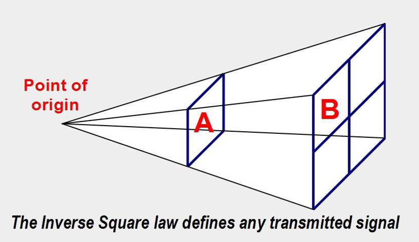
If a transmitter is located at the point-of-origin, Square B only receives one/quarter of the energy that Square A is exposed to.
This effect applies to any point source of radiation in free space, including daylight from our own sun. To the Amateur, this rule tells us that if no other factors are in play, an operator would have to quadruple their transmitter power to maintain the same signal strength at double the distance from the source.
Another aspect of importance is a firm understanding of what a signal strength meter on a receiver is really telling us. Certainly we know that Signal Strength meters are relative indicators of signal intensity. High ‘S’ point readings are always going to represent a superior signal over lower values.
The maximum reading is notionally S9, with greater readings being expressed as 10, 20, 30dB etc. stronger than an S9 signal. (It is not ‘Strength’ 10, 20, 30…)
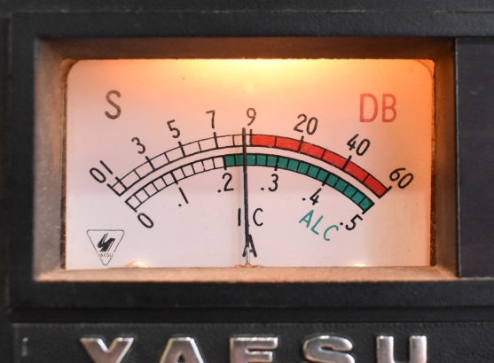
The key to numeric signal strength reports is that each S-point represents a 6dB change in signal. On a properly calibrated S meter, a distant station would have to double their transmitter power twice for a received signal strength meter to rise from say Strength 5 to Strength 6.
These facts help us to understand the relationship between transmitted and received signals and allow us to view the anticipated losses of our antenna feedlines in the correct context.
Common Coax Feedlines
The image below shows four of the most common variants of shielded coax cable used by amateur radio operators. As is often the case, you get what you pay for. The thin RG58 can be purchased at around $2 (AUD) per metre. To the far right, a fresh run of LDF450 corrugated cable will set the station owner back by around $9 per metre. Connector cost is also a factor here. The humble PL259 plug for the cheaper, thin cable is only about $3, but the price of a machined connector for the LDF450 is going to start at around $35 per plug.
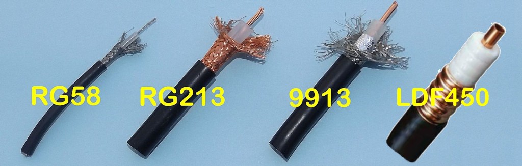
There is more to the selection of a cable than just losses. While the 9913 and the LDF450 are excellent low-loss cables, they lack flexibility and are not appropriate for running through the interior of a car, or looping around an antenna rotator on a tower.
The losses in coax cables are cumulative. The longer the feedline, the greater the loss. If the requirement is a short run in a vehicle between transceiver and antenna, the convenience of the thin and flexible RG58 usually outweighs the minor losses involved. Coax cables are also subject to the Skin Effect. As the frequency used reaches higher up into the spectrum, the RF currents will tend to flow more through the outer surface of a conductor rather than through its centre. UHF conductors such as LDF450 have a hollow centre core, since any extra metal inside would provide no great advantage to the cable performance at UHF
Cable Testing while Transmitting
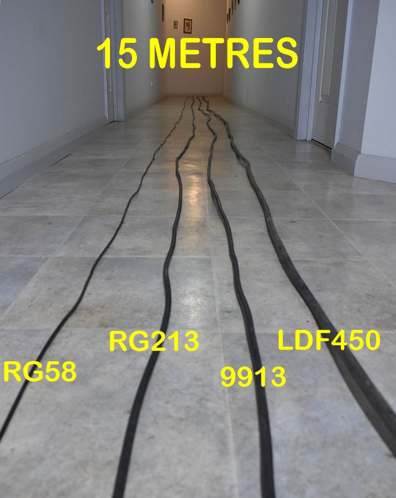
For this analysis we worked with fifteen metres of each cable type, RG58, RG213 9913 and LDF450. 15M is an average length for most installations that involve a modest mast or tower, plus a few horizontal metres to reach a nearby shack space.
There are many variants of these cables between coax manufacturers and there will be some small variations in performance between them. For example, RG8 is quite similar to RG213, except that it has a higher temperature rating.
The 9913 is a low-loss cable with a solid centre core that has a layer of copper braid over a layer of foil. It has excellent performance, but it is harder to work with.
One of the difficulties with comparing cable specifications is that data sheets often only quote dB loss figures on spot frequencies such as 100, 200, 400 MHz. This information may only be applicable to 100 foot lengths of the cable product, which in turn can be confusing when trying to relate the figures back to Amateur Radio cable runs and frequencies.
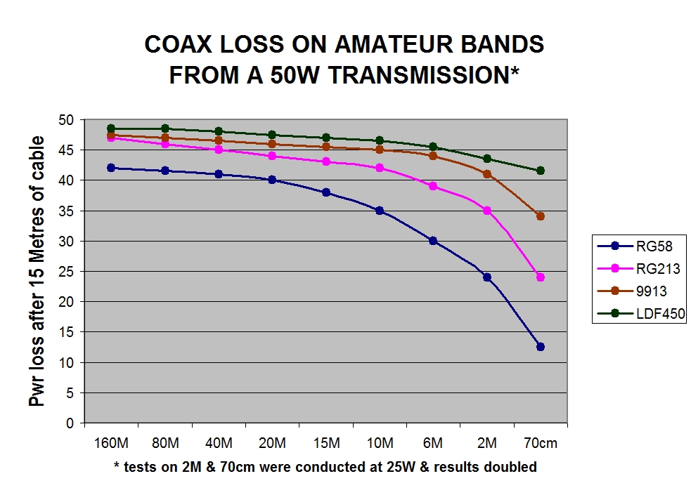
This study does not rely on commercial data tables. The 15 metre long sections of four cable types were laid out in a long hallway. Fifty Watts of RF was transmitted through each cable in turn into a dummy load. This test was repeated for most Amateur bands from 160 metres through to 70cm and the results logged in a spreadsheet. With each test an RF power meter was first placed at the transmitter end for calibration purposes, then relocated to the distant end of the cable for a second measurement. This recorded how much RF would actually reach a correctly matched antenna. In our case the antenna was a good quality 50 Ohm dummy load.
The test results give us an excellent window of understanding into the most appropriate coax cable types to look for when setting up a new station, or upgrading an existing one.
The above results have been extended to the table below, where the values are expressed as a percentage figure of power lost in our four 15 metre long test feedlines. Power losses of 20% and higher have been shown in red.
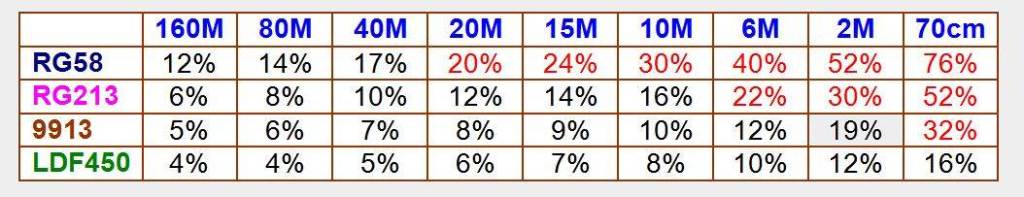
This table tells us that for the bottom end of the HF part of the spectrum, the losses of the cheap RG58 are around 15%, which are probably acceptable for general operations. The same cable on the 2 metre band is quite dismal, with more than half of the transmitted power being lost in the feedline. On UHF, a tower run of RG58 is pretty much unusable.
The table also reveals that unless extra shielding is required to overcome feedline interference, using the thicker low-loss coax at the bottom of HF is probably an unnecessary extravagance.
Cable Testing while Receiving
It’s fair to assume that if a feedline exhibits major losses while transmitting, then that same cable will also have an impact upon reception performance. In practical terms, it is difficult to quantify receiver losses in coax, unless real on-air comparisons are made using typical receiver hardware. It was therefore reasonable to conduct another series of tests on reception effectiveness using these same four cable types.
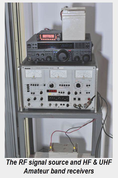
For this experiment, we used a Shlumberger HF-UHF test set to generate a stable RF signal into the test receivers at a fixed reference value. A medium signal strength of ‘S5’ was selected. In separate tests, the four test feedlines were inserted in series with the signal source to determine the signal impact upon the reference signal. This process was repeated on the common bands from 160 metres through to 70 cm.
It should be noted that we could have provided higher resolution data by receiving the test signal on our calibrated spectrum analyser, but this result would not easily relate to the everyday experience of received signals by Amateur stations.
Hence the spectrum analyser was put to one side and we used a Yaesu FT950 for bands 160 through to 6 metres and an FT8900 for 2M and 70 cm, both receivers were powered by independent 12V battery supplies.
The use of conventional transceivers for this receiver test meant that the results would be of fairly coarse resolution, in that it was difficult to measure increments of less than half of an S-point. As per the chart below, the experiment was still able to give us definitive results.
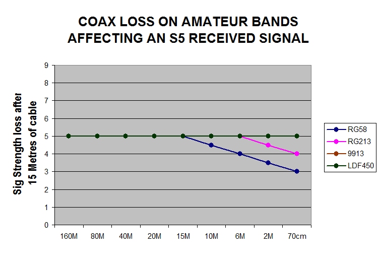
The outcome was a little surprising in that all four cable types had no measurable impact upon received signals on the 15 metre band and lower. The cheap RG58 cable began to manifest a small reduction in signal strength 10 Metres and above, but even on 70cm, it was only two S points down from the same test with a quality cable.
This is telling us that while the cheaper cable has measurable losses on VHF and UHF, most operators will not be aware of this reduction, particularly if the received signals are strong.
Where have all the Losses Gone?
 While these charts show that energy is being lost in a feedline, it does not disclose how it is lost. Ohms Law on resistance still applies to RF energy. The thinner coax has less copper in it and this provides higher series resistance than the heavier coax. Therefore much of the RF energy lost will be dissipated as heat within the resistance of the cables. A sufficiently long run of RG58 at UHF will behave as a dummy load.
The cheaper coax also has tiny gaps in the braid that accumulate over the length of a cable, which means that a portion of the lost energy will be directly radiated from the feedline.
Mostly this is insignificant, but it can be a factor for interference to and from a transceiver.
If some RF is radiating from the cable at ground level, it may lead to interference problems such as attacking domestic sound systems, or resetting a home internet modem. A poorly shielded coax feedline can pick up ground level interference from Switchmode power supplies and LED lighting drivers, manifesting as a few unnecessary S-points of receiver noise. Where interference events do appear within a home antenna installation, it can be worthwhile swapping to a low-loss cable with superior shielding, not just for the higher output power at the antenna, but for its potential to reduce interference issues
Some Coax Cables are designed to have Losses
It may seem to be counter-intuitive, but there are instances where lossy cables are necessary. A good example of this are RF systems in underground railway tunnels where trains are required to maintain radio contact with a control room. There is a species of cable that looks like LDF450 but is actually a product called ‘Radiax’, which has perforations in the copper shield under the PVC outer coating. It was designed for RF distribution through places like tunnels and cannot be used as a feedline. The point is raised here because some off-cuts of such cables have found their way into second hand radio markets. Any amateur who unwittingly purchases a Radiax cable to feed an antenna system is bound to be disappointed with its performance.
Conclusions
As described at the outset, the information presented here is the result of practical experimentation. Different cable brands in different physical condition may yield better or worse results, but in general terms, the effects revealed in these experiments would be commonplace.
Our tests focused on a fifteen metre cable length as being typical for many home installations. Longer or shorter cable lengths will produce a proportional loss or improvement in performance.
The aim has been to quantify the real impact of common cable types on actual amateur bands. Not just data-sheet losses expressed in portions of dB on fixed points of the radio spectrum. We have also observed that it is important to not obsess over a few watts of loss here and there. As shown on the Inverse Square Law model at the start of the article, it takes a substantive shift in power level to produce a meaningful change in signal strength at the receive end of a contact.
