P246
Mobile Antennas
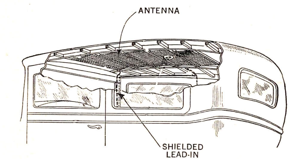
Amateur radio antennas for vehicles are a difficult topic. There is a near endless selection of articles and videos that focus on branded antenna and comparisons. These tend to be long on product endorsement and short on antenna theory. As long as cars have been on the road there has been a demand for the perfect mobile antenna. This quest is ongoing. Early vehicles with wood and fabric roofs fitted mesh sections for radio reception, yet such assemblies were horribly inefficient.
While it’s true that transmitter antennas must adhere the principles of impedance and resonance, vehicle mounted antennas have other important parameters to satisfy. Unfortunately the physical requirements are usually detrimental to performance. Any antenna placed on a vehicle will always be a compromise from perfection.
Here are some of these parameters:
- Must be near- omnidirectional
- Usually vertically polarised
- Must not be too high
- Must survive at high speeds
- Must not flex too much at speed
- Must survive occasional encounters with trees and foliage
- May need to be removed or lowered for garage parking
Like the antennas themselves, some of these rules may be bent, or even broken in the quest for improved performance. This 4-element cubical quad antenna for the 6 metre band is not only impractically unidirectional for a mobile, it’s also unfriendly for garage parking and drive-through retail outlets. Some may regard such projections as ‘ugly’, but like so many other situations, beauty will always be in the eye of the beholder.

Directionality and Polarisation
The first two items from of our list say that mobile antennas should be omnidirectional and vertically polarised. Turning corners is something that cars do as lot of. If directional antennas were used, it would result in a major loss of signal. Constructing tough, horizontally polarised antennas that radiate in all directions simultaneously is not easy. While these antennas can be made for UHF and higher frequencies, the size of such HF antennas could mean that someone looses an eye. Vertical antennas solve this problem. Vertical antennas can send and receive in the horizontal plane while on the move and signals can remain relatively constant without too much variation while navigating traffic. By convention mobile communications is conducted with vertical polarised antennas, even if this means antenna gain is compromised. The height of any HF mobile antenna is going to have size constraints. Drive-through bottle shops still have fluorescent lights and Melbourne
still has tram lines. Plenty of operators will recognise the noise associated with entering a home garage without first un-screwing or lowering their antenna.
Ground Plane effects
The placement of a vertical antenna on a vehicle has a significant effect on how it radiates and receives from different directions. Most vertically polarised antennas are going to be using the metal body of the vehicle as a ground reference. A lack of ground plane in a given direction will cause deterioration of signal in that direction. The following image demonstrates how mobile antenna placement can distort the radiation pattern.
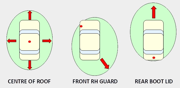
Ideally, placing a vertical antenna in the centre of a roof will produce a more balanced pattern. Other locations compromise that pattern. Most vehicles tolerate this reduction in performance through expedience of where an antenna may be placed without drilling holes in bodywork.
The example in this image shows the HF antenna on the bulbar and the VHF/UHF vertical on the bonnet edge. These are common choices, prioritising practicality over optimal placement.

Bullbar Bonding
While bull-bars are a solid foundation for antenna mounts, many installers neglect additional grounding between the bull-bar and the vehicle body, leaving the ground path very low to the vehicle. This creates a significant interruption to the ground plane that results in poor performance and radiation pattern distortion that many operators are unaware of.
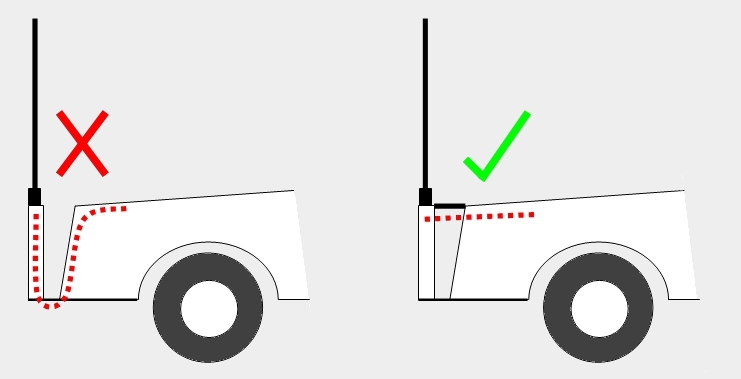
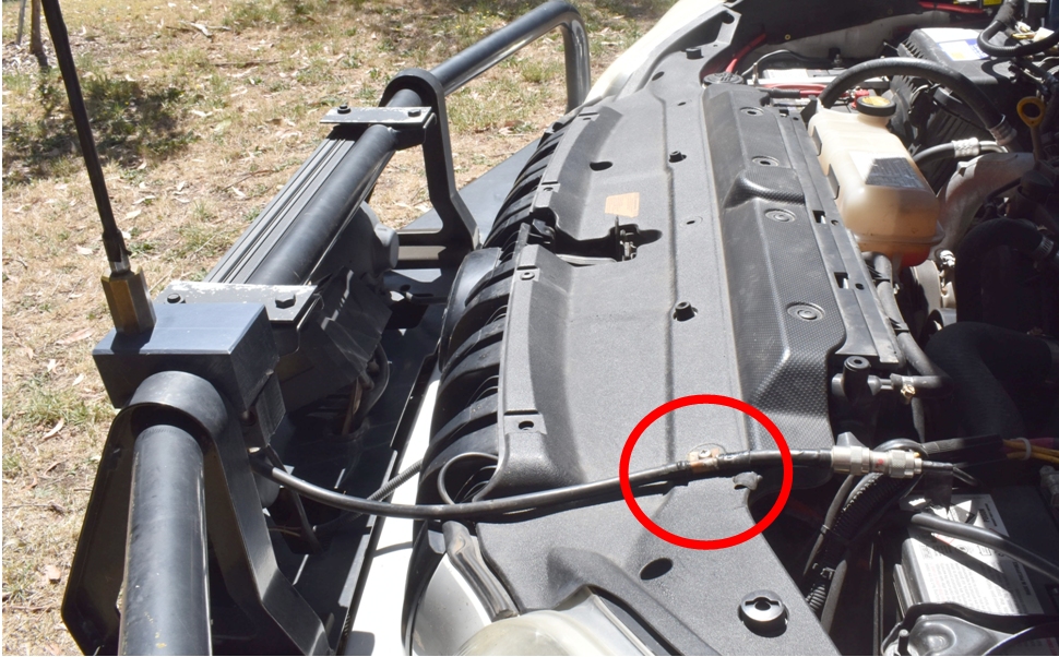
In the sketch above we can see an example of a bad and better installation where electrical bonding between the body of the vehicle and the bull-bar has been added. This can be achieved with a copper strap or by bonding the coax braid to the vehicle close to the front, as shown (circled in red) below:
Loading Coils on mobiles
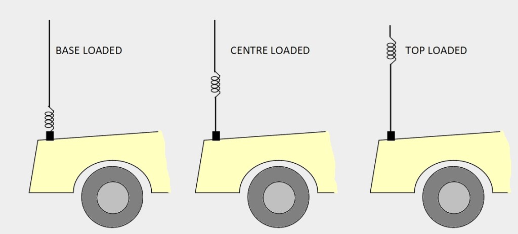
A quarter wavelength vertical antenna on the 20 metre band is about 5 metres long. This is too tall to be practical on a vehicle in a world of low power lines, hence a reduction in length is essential. To make vertical antennas shorter, loading coils are used. Such coils can be placed at the top, bottom or centre of a mobile antenna, or in the case of ‘Helical’ antennas, wide spaced windings are applied over the full length of the antenna.
Placement of loading coils are another area of compromise. Antennas with a coil at the base, or ‘Base Loaded’ antennas are mechanically convenient because the weight and wind-loading of the coil is close to the vehicle, but unfortunately it will reduce the antenna performance.
HF mobile vertical antennas try to mimic the performance of a true quarter wave ground plane. A characteristic of the quarter wave antenna is that the transmitted RF current is highest at the feedpoint, reducing to zero at the tip of the antenna. Unfortunately, the presence of a loading coil creates a serious disruption to this current curve. Consider the four plots below showing a vertical antenna and its transmitted current distribution curve.
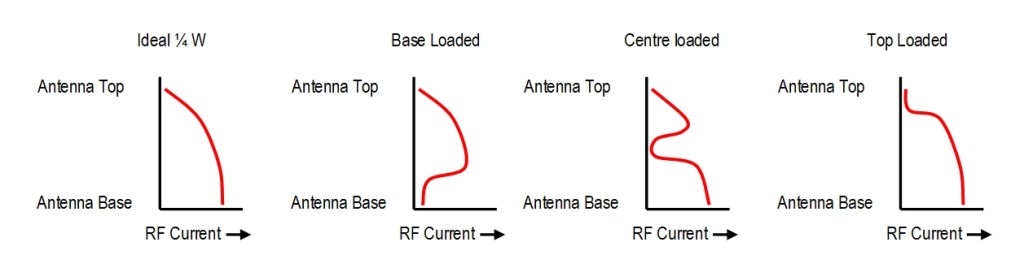
To the left we show the curve on a genuine quarter wavelength ground plane, with high current at the base and zero current at the tip. Where a base loading coil has been added to shorten the antenna, even though it is resonant, much of the premium RF radiated current is lost within the coil. A centre loaded antenna is somewhat better, but still a compromise.
Top loaded antennas provide minimal disruption to this current curve and will provide superior performance. It will out perform a base loaded antenna with the same overall length. Despite this effect, many expensive and automatic base-loaded motor-tuned HF antennas are used. They may look very impressive, but performance will always be reduced by this design.
Many multi-band mobile antennas are sold with will a spiral of wire wound over its length, with plug-in tappings at intervals that permit band changes without physically swapping the antenna.

The Good the Bad and the Lumpy of Top Loaded antennas
Unfortunately top loaded antennas suffer from higher wind drag while moving and can encourage pendulum-like antenna sway, making them an unpopular aesthetic choice, however, many are still sold.
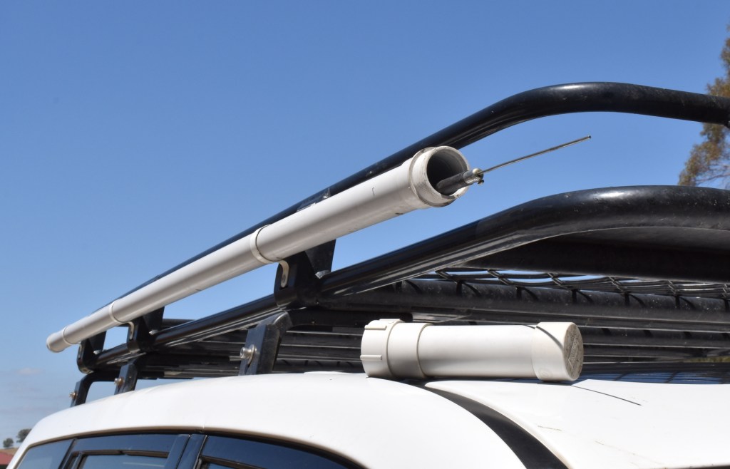
If HF mobile performance is the highest consideration, the best solution is to have several different top-loaded antennas, one for each band of use, then physically swap the entire antenna whenever the band is changed. This does require the driver to carry and store all the unused antennas somewhere, resulting in storage problems. One way to solve this is with an antenna storage tube on a roof rack that can hold a full set of HF antennas.
VHF/UHF radiation angle (5/8 vs 1/4 wave)
Antenna gain is always nice to have. With ominidirectional vertical antennas some gain can be achieved by lowering the radiation angle of the antenna. A 5/8th wavelength antenna will have a lower radiation angle than a basic 1/4 wave antenna, meaning the 5/8th will give better transmission range between two vehicles on a highway.
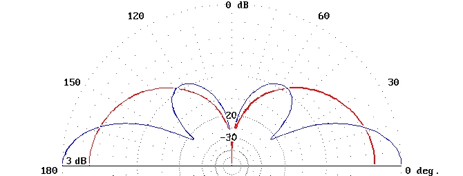
Operators should be aware that the 5/8th wave antenna is not always the best option. In the above plot the red curve shows the radiation angle of a 1/4 wave antenna and the blue shows the higher gain 5/8th wave angle. If the remote station is on a similar plane of elevation, the 5/8 performance is great. Where the distant station is on top of a hill, the lower radiation angle will reduce hilltop reception and reverting back to a simple ¼ wave antenna will outperform the 5/8th. This is not to say that operators should not use higher gain antennas while mobile, as most of the time the 5/8th is still the best choice. Still, it may be useful to carry a spare ¼ wave antenna for situations of mismatched elevation if working a station or a repeater that is situated high above your current position.
VHF/UHF antenna brackets
There are not a lot of places to mount an antenna in small cars. Larger cars can use z-shaped hood mount brackets with fair success. One of these can be seen below where a dual band 2M/70 cm antenna mounts on the edge of the engine bay and passes through the gap of the closed hood.

Where the vehicle has a hatchback rear, antenna mounts are difficult but not impossible. This bracket was fabricated from a folded plate of 3mm aluminium. It also supports a dual band VHF/UHF antenna. As previously noted, it is not an ideal location for radiation pattern, but it is discrete and still sufficiently low to permit passage into most garages without first having to stop and unscrew the antenna.

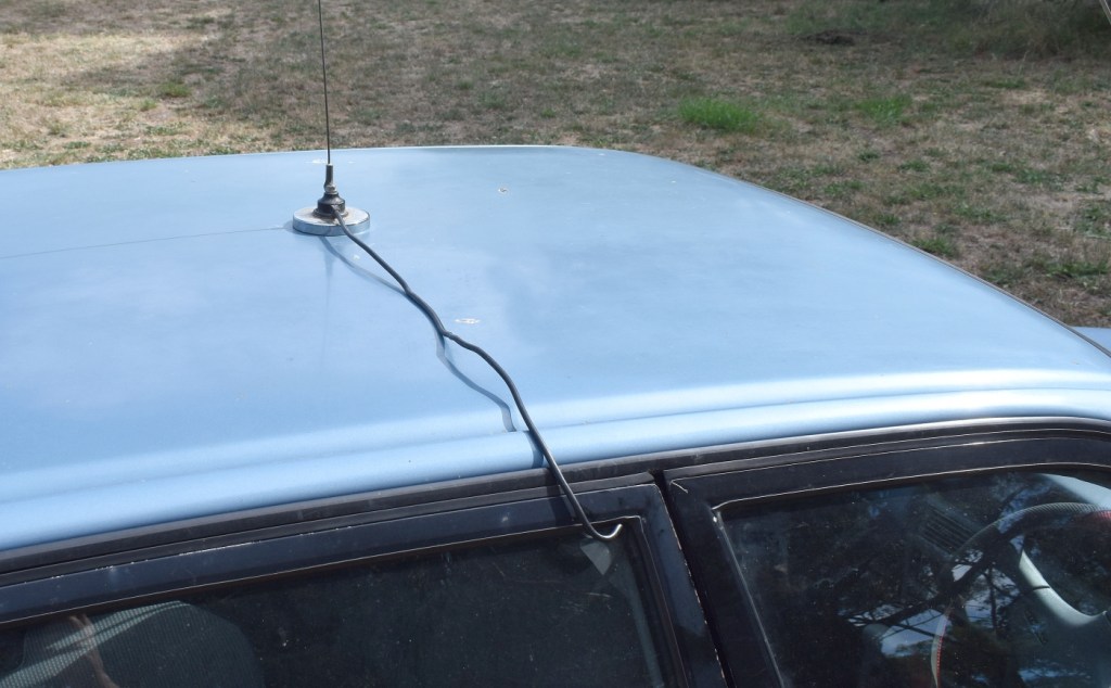
Magnetic base antennas are a surprisingly good alternative
Where a vehicle is hired or on loan, the classic magnetic base antenna is very effective temporary installation. Placed in the centre of the roof, perhaps through some plastic film for paint protection, it’s position can out-perform many permanent installations on the edge of a vehicle.
The best path for the coax cable is in the driver side rear-door window, with a small drop-loop to prevent water from following the cable. This rear off-side door is generally the one least used and is the most distant from roadside shrubbery.
Summary
Mobile operation has always been a major part of Amateur Radio. In terms of performance, there are good and bad mobile antennas, but few of them are great. For HF it will still be better if you can unroll some wire and coax and extend the antenna into some trees, but that won’t help you on a freeway.
The choices we make when fitting out a vehicle will still determine how well we communicate while driving. Be prepared to experiment and find solutions that will work the best for your own situation.
