P253
Constructing a HF Curtain Array for the 20 Metre band
Around every 12-18 months a field event called Antennapalooza is staged about 80km East of Melbourne. This is a fun weekend where visitors can bring caravans tents or swags and set up in an empty field for two days. There is a pavilion, some lectures and demonstrations and time to catch up with friends. At night there is a camp fire and an opportunity for take-away pizza. The 2025 event was the ninth Antennapalooza and about 75 persons attended over the two days. Each year there is a theme to be explored, with a focus upon projects that would be hard to do in a suburban backyard. On the lead up to the 2025 event we wanted to try something a bit more unusual. The challenge was could we build a Curtain Array for HF?
A little background is needed here. Curtain Arrays were usually made by governments to service high power, long distance communications. Different varieties started to appear about a century ago. There were Sterba Curtains, Bruce Array’s and others. They were huge. Typically stretched between 100 metre high towers, they were a tangle of wires and cables. Essentially they were clusters of dipoles phased together in matching orientation, fed by open-wire feedlines. These were first designed in radio pioneering times and many such arrays were not very efficient, but big transmitter power could compensate for that.
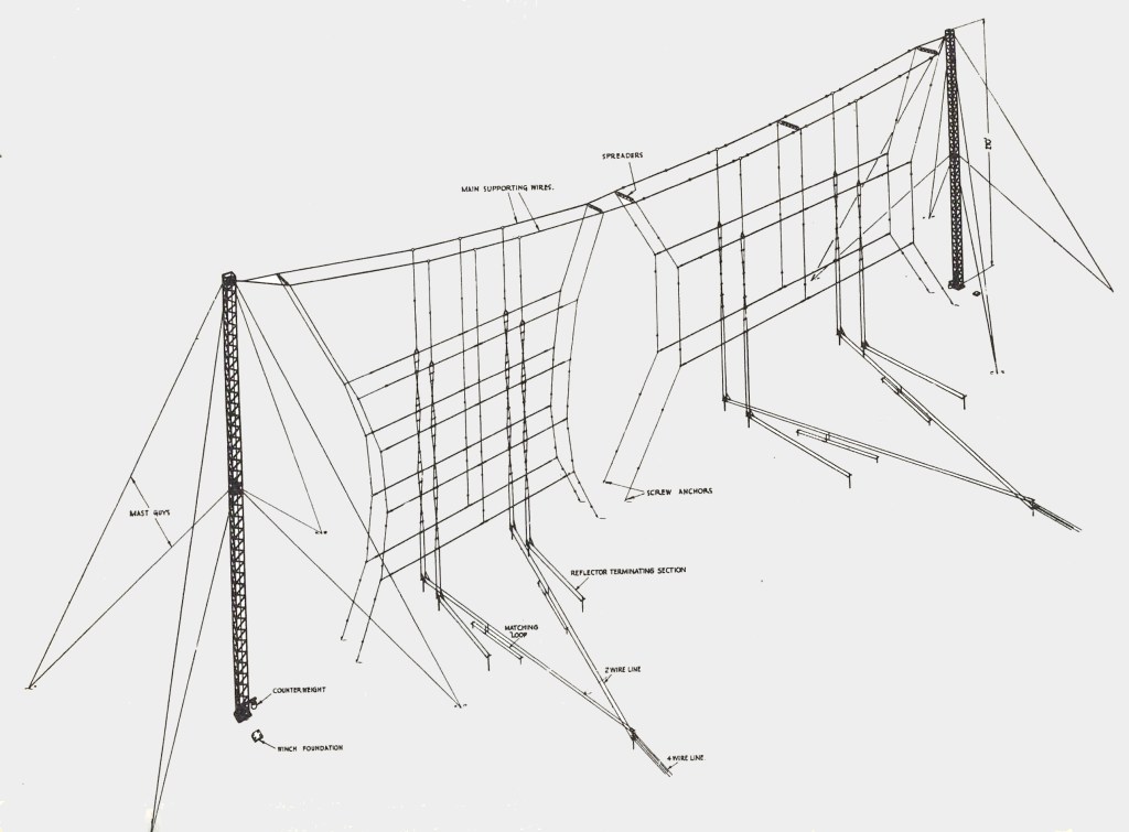
The image shown here was a Radio Australia a curtain array located at Lyndhurst, South-East of Melbourne. It was a serious monster antenna, spread over about 5 acres of land. It was used for overseas broadcasts on 9, 11 and 15 MHz. These were not for the faint hearted!
Our challenge was: Could we build a low-budget baby curtain array on the 20 Metre band to play with for just a couple of weeks? Could we make it work? Could we have it ready in time for Antennapalooza?
The preparations began…
If we could stand up some poles about 20 metres high, with pulleys at the top, then maybe we could hoist up an arrangement of eight dipoles on 20M, each with a matching reflector element for forward gain.
I would like to say that we did all sorts of 3D modelling and high-res CAD drawings, but our master plan was a hand-drawn sketch on the back of an old envelope and we just worked with that.
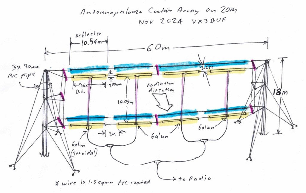
his baby curtain array was still going to need 60 metre spacing between the poles. There were advantages to going with folded dipoles instead of simple dipoles. The feedpoint impedances were higher and this would be a better match for the vertical lines coupling the lower dipoles to the upper dipoles, a half-wavelength higher. The reflector elements were wire, 5% longer than the driven elements, three metres away. Essentially it was a group of eight 2-element beams, all pointing in the same direction.
Next we had to pick a direction. From South-Eastern Australia, Short Path to Europe seemed like a good idea at the time. A few lines on a Google Earth map showed us the way and this was converted to some pink spots sprayed onto the ground with marking paint. It looked like this:
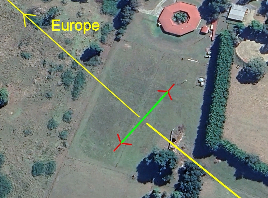
Our land at Drouin West has a down-hill slope towards a creek, which meant that one pole was going to be higher than the other. We dealt with that problem by ignoring it. This positioning also meant that it was going to straddle a barbed wire fence. That was trickier because cows and antenna guy ropes are not a good mix, so an electric fence was arranged around the southern pole.
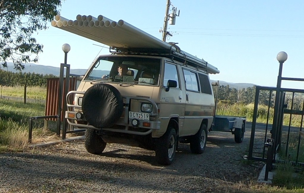
With a plan in place the next step was organising materials – on a budget. In 2015 we tried out a Rhombic antenna on poles 12 metres high made from single lengths of 90mm PVC stormwater pipe. That had sort of worked ok. By sort-of it meant that some big winds did break the posts. New plan. These PVC pipes are 6 metres long and $22 dollars each. If we taped three of them together with duct tape, then stacked three more on top, then another three more on top of that, we would have 18 metre tall posts. What could possibly go wrong? A quick trip to Bunnings brought home 18 lengths of pipe, ready to go.
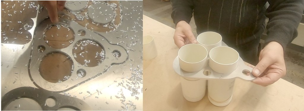
These poles were going to need guying points, plus somewhere for the antenna pulleys to attach. That was a bigger problem. I consulted a friend in a nearby factory and we were able to machine out six aluminium guying plates out of 6mm sheet. Looking good.
A lot of rope was going to be needed. Ebay had 400 metre rolls of telecom rope for $40 each. We used up three of those. 1200 metres of rope was about right.
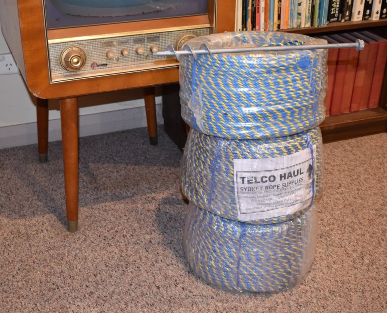
We knew there was going to be a lot of stresses on these ropes and they had to attach to the ground somehow. We had previously used spiral ‘Ground Grabba’ stakes for the Antennapalooza pavilion and they worked really well when used in pairs, screwed into the sub-clay with a little bit of chain between them to share the load. They were expensive, but essential. These were ordered in from Queensland. One of these can be seen on top of the rope stack.
Next we needed a whole mess of wire. About 350 metres of it. I scrounged up a roll of 1.5 square mm plastic coated electrical cabinet copper wire, but I needed more. I visited a nearby electrical contracting company and asked nicely for any dregs of half or quarter reels in whatever peculiar colours had not been used in the past decade and collected enough wire to do the job. Historically Curtain arrays were always fed by open wire feedlines on posts. That looked really complicated and I didn’t want to do it. Instead we went with 1:1 baluns at the four lower feedpoints, Tee pieces and a mess of 50 ohm coax cut to half-wavelengths on 20 Metres. We used most of a roll of RG58 and a bunch of PL259 crimp connectors. (Yes, we did compensate for Velocity factor) The advantage of the manifold feed system with Tee pieces, that if you fool around with lengths somewhere between quarter and half wavelengths, you can get some nice impedance transformation action happening and establish something close to 50 Ohms at a common feedpoint. Later on , this also lets us hoist the antenna and unplug the coax to cut the grass with the tractor. Curtain arrays laying in the grass, meeting slashers on tractors would not end well.
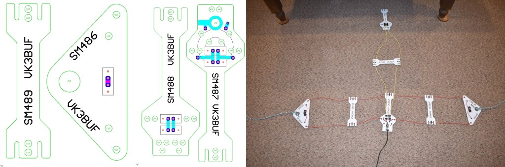
There was just one more missing ingredient. The brackets to connect the ropes to the wires and the coax. This was a tricky one. However I am a big fan of circuit board design, so I drew up feedpoint terminal blocks, dipole ends and spacers to be machined from 3mm thick circuit board material. I emailed the file to my favourite producer in Shenzhen and they turned up a few weeks later. Upon their arrival a small non-resonant mockup was made to test the mounting points and cable tie holes.
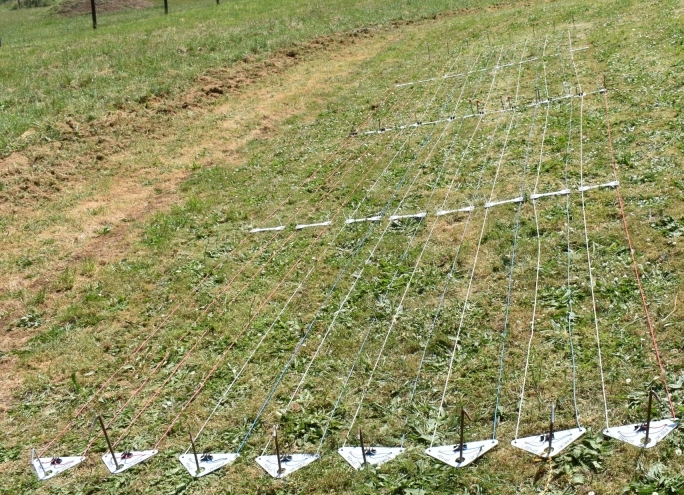
By now we were getting closer to Antennapalooza, then scheduled for November 2024, so I had to pull a finger out and get building. Step one here was to build a folded dipole, get the length right using a Sark antenna analyser, (compensating for the PCV insulation) then make seven more of them just like it. These were laid out on the ground between tent pegs to confirm the lengths.
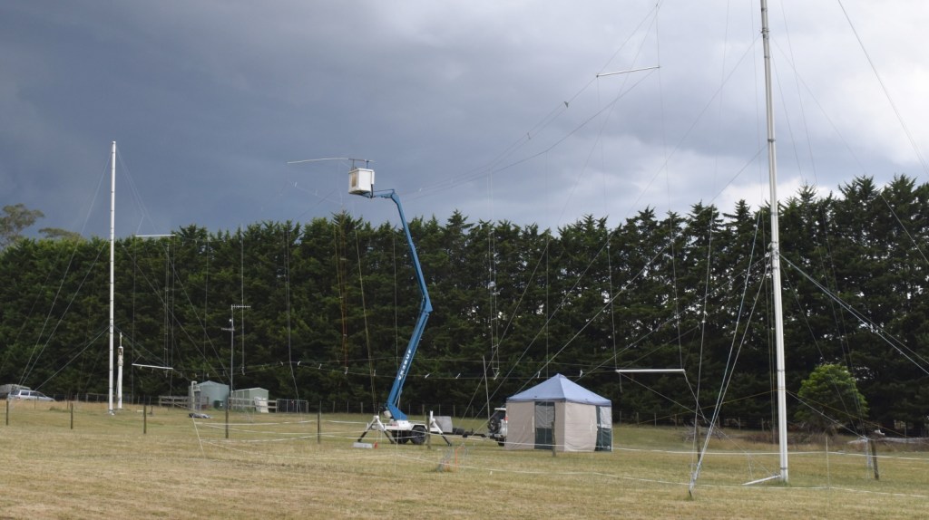
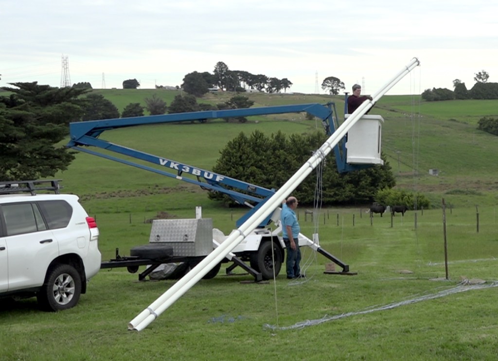
The work was becoming more physical and we were getting into the warmer weather. The grass was cut low in the antenna area. All the ground anchors were screwed down hard on the pink spots and the poles had to be stood up. Fortunately we have the services of a boom lift that I rescued a few years earlier and refurbished. Great for tree trimming and instant portable tower, but it only goes up 12 metres.
We joined the first two stages together with more duct tape, prepared the guy ropes. Dianne VK3JDI in the boom lift wrapped her arms around this assembly while I sent it all up 10 metres into the air. Then I was able to run around and apply truckie rope hitches to all the guy points. That worked pretty good, so we did the same for the second post.
Getting the third stage up was a bit harder because the boom lift could barely reach past the 12 metre mark, meaning we could only hold the third stage from the bottom. This required the fabrication of a tricky PVC pipe clamp which was attached to the boom lift bucket. More volunteers to hold guy ropes and with some choice words, it all went up ok.
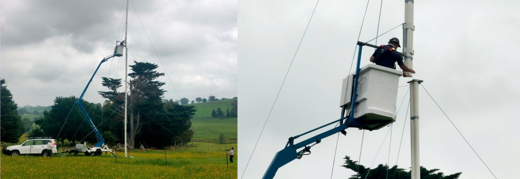
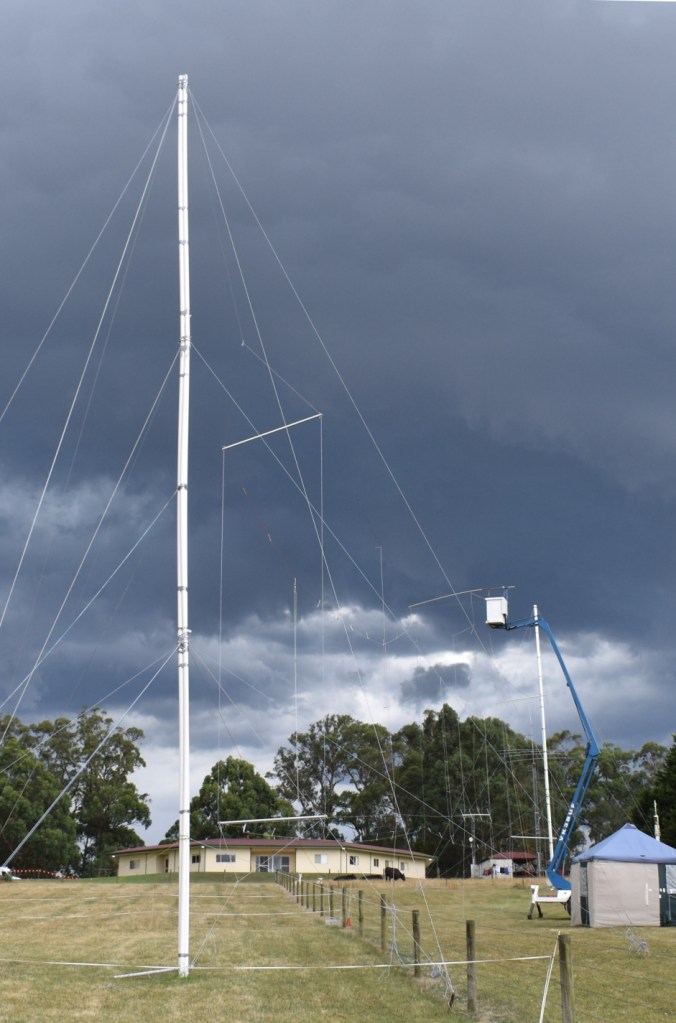
Now we were cooking. The poles were up and the antenna was assembled on the ground, ready to haul into the air, just in time for the field weekend. One more problem became apparent. Because the poles were plastic, there was a limit to how much guy rope tension could be applied. The array sagged a bit in the centre. Ideally we would put up a third pole. Instead, we cheated and just used the boom lift again.
The 1:1 balun and manifold feed system of coax worked pretty good. The antenna analyser said that we were resonant and impedance was well within range of the transceiver antenna tuner.
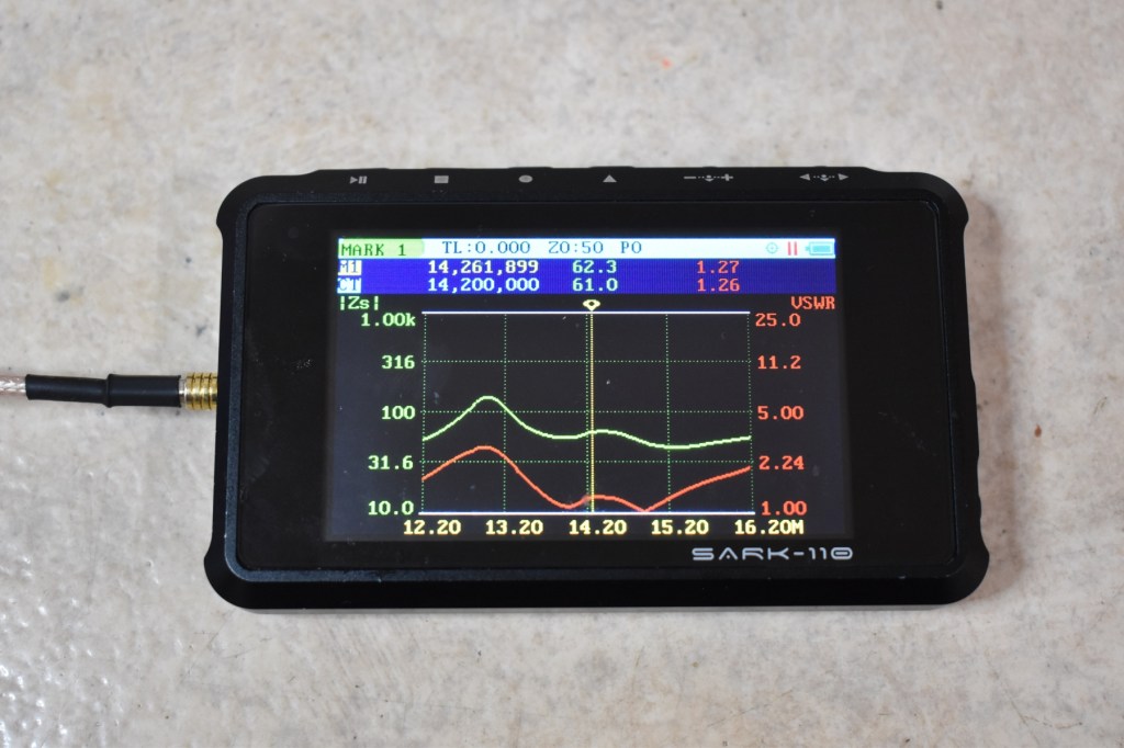
There were two dips on 20M. One for the dipoles and one for the vertical phasing harness between the dipoles. Impedance was around 60 ohms. Close enough. We were ready to go!
Two days before the field event was to commence, we received the news we had been dreading. The weather forecast was for high winds and 40mm of rain over the advertised weekend. This was not good. We had done the drowned rat and bogged car thing in previous years and it was not going to be fun if we proceeded. Emergency emails went out and we postponed the event until January 11, where we could cross our fingers once more. It also meant that we had to keep this monster in the air for 2 months over Christmas and not the planned 2 weeks.
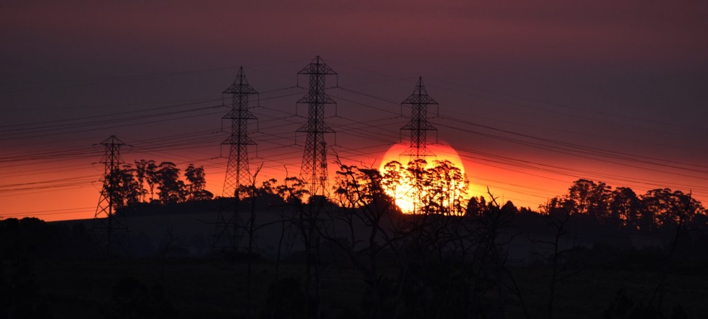
The image below was taken only one hour before the ‘final’ image at the end of this page.
There were some pretty big storms during that time and hot days approaching 40 degrees C where the poles tended to soften. We were now in high summer. The grass had changed from green to brown and there was also a few bushfires popping up around the state, making for some hot, smoky, but spectacular sunsets through distant power lines.
Five days before the new Antennapalooza 2025 date, another big storm front passed through and dropped one of the posts of the curtain array. It was out with some PVC pipe joiners, glue and a hacksaw and the mast went back up, only 400mm shorter than before.
The restored antenna worked well. The 20M band was solid with CW and SSB stations. A couple of the visitors operated drones and got some excellent wide shots of the antenna. This image is courtesy of Peter VK3DEL. The wires have been artificially highlighted as they tend to disappear when photographed against the grassed background.

A 3 x 3 metre gazebo was erected to contain a table, the HF rig and a few chairs. The ‘Shack’ was working well. Many contacts were made over the weekend. Jordan VK3ACU made a recording of the extensive CW activity on 20M. There were hundreds of stations. You can watch this at: https://www.youtube.com/watch?v=4I9E2sSa674
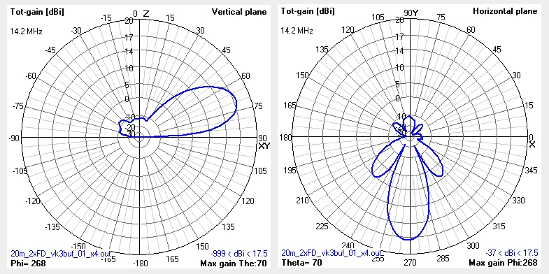
A local Amateur, Dieter VK3FFB was able to construct a software based model of this antenna as a means of anticipating its performance. Notionally it had a forward gain of 17.5 dbi and a peak radiation angle of around 20 degrees from horizontal. We had plans of conducting tests to see how closely the antenna would follow the model, but fate intervened before this could be done.
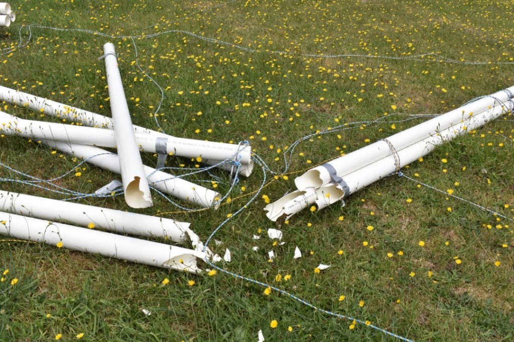
On the Sunday afternoon, after the last presentation, visitors were packing up and heading home. That’s when another storm front hit. This one was wild. Peak gusts were around 90 kph. This was too much for one of the posts. The lateral stresses were huge and the South end of the array came crashing down. Geordie VK3CLR was quick enough to capture video of this event from some distance away.
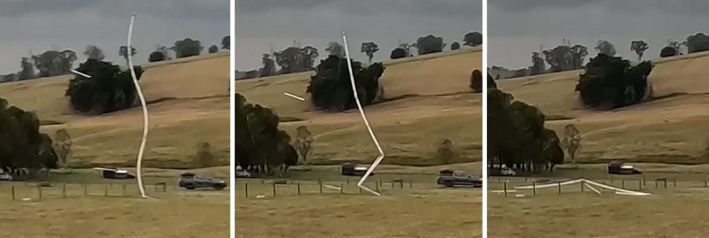
This was unfortunate, as while the antenna survived the main event, the plan was to operate it for another few weeks and carry out additional performance tests. The region around Melbourne is notorious for its high variability. It can go from cloud free and sweltering in the mid 30’s to hailing sideways in high winds, then back again to a stillness friendly to birthday cake candles – all in one day. This had been a particularly variable season and the array had survived a tremendous amount of this chaos, only to come unstuck when the weekend was coming to a close.
Over the next few days the second pole was (carefully) dismantled and all rope and wire was bundled into boxes. The cows had free reign of the land once more. (Or at least for another month before they graduate to hamburger heaven.) Although the antenna usage was brief, the process of constructing and testing this antenna was a fruitful learning experience. The process undertaken here makes one have respect for the work (and the budget) that goes into the giant HF commercial arrays, usually viewed from a distance. Taking the time to apply such a structure to an Amateur band was a load of fun. It only happened through the labour and encouragement of many amateurs. Ultimately this is what our hobby is all about.
Supplementary Links:
An interview about the antenna and drone footage:
https://www.youtube.com/watch?v=oyYqoTKnL5s
Drop Table Adventures clip about Antennapalooza:
