P254
TTL and CMOS Logic Devices
Take a close look at any circuit board manufactured between 1980 and 2000 and you will probably see some oddly numbered IC’s like the CD4081B device shown below, both as a DIP package and its surface mount counterpart.

These were the building blocks of electronic logic systems that may work in conjunction with microprocessors, or as stand-alone circuits. They formed a bridge between the academic Boolean Algebra and the real world – without the need for software.
The logical building blocks
As transistors and solid state diodes were being developed in the 1950’s it became apparent that the functions that the perform could be reduced to logical building blocks. The most basic devices were branded AND, OR and INVERTER or NOT gates.
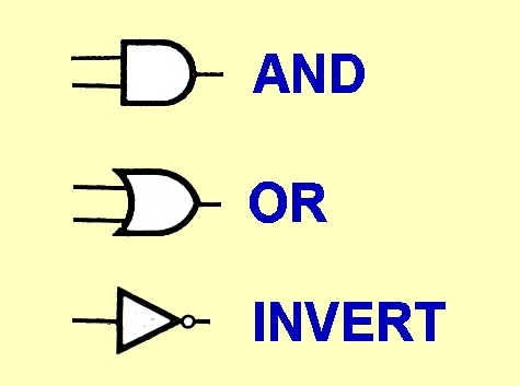
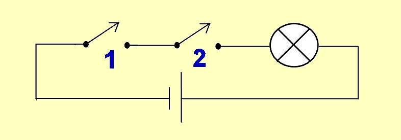
The AND gate had a low voltage output and would only assume a high state (+5Volts) if all of its inputs were also at a high state. This can be demonstrated by this switch assembly where the lamp (the output) will only glow when both Switch 1 AND Switch 2 are closed.
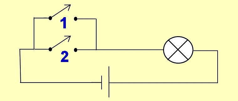
The OR gate would provide a logical high output if any of its inputs were active in the high state. This effect is replicated in the circuit below where the lamp will glow if Switch 1 OR Switch 2 is closed.
The third building block is the INVERTER or NOT gate where the output state is always the opposite of the input. This effect can be produced by a single transistor where a voltage applied to the base activates the transistor, causing the output to switch from a positive voltage down to approximately zero volts.
These three building blocks form a kind of electronic Lego where many blocks used together can create quite sophisticated logic systems. An AND gate with an inverter tacked onto the output became a NAND gate
The Birth of TTL
TTL is an abbreviation for Transistor-Transistor logic. The first devices were launched in 1963. Texas Instruments created a family of logic devices called the 7400 series which were later replicated by many other manufacturers. One Integrated circuit could have 4 or 6 independent logic gates to be used as the designer saw fit. These were expanded within the chips to form complete Flip Flop latches and counters. All devices operated on a common 5V power rail. There were variants which had faster reaction times or wider temperature tolerances. With the standard series, each device began with a ‘74’ prefix and would work from 0 to 70º C. The military version was similar but it would work from -55 to +125º C and had a ‘54’ prefix instead.
Once the 74 or 54 was identified on a device, the next digits would tell you what the device actually did.
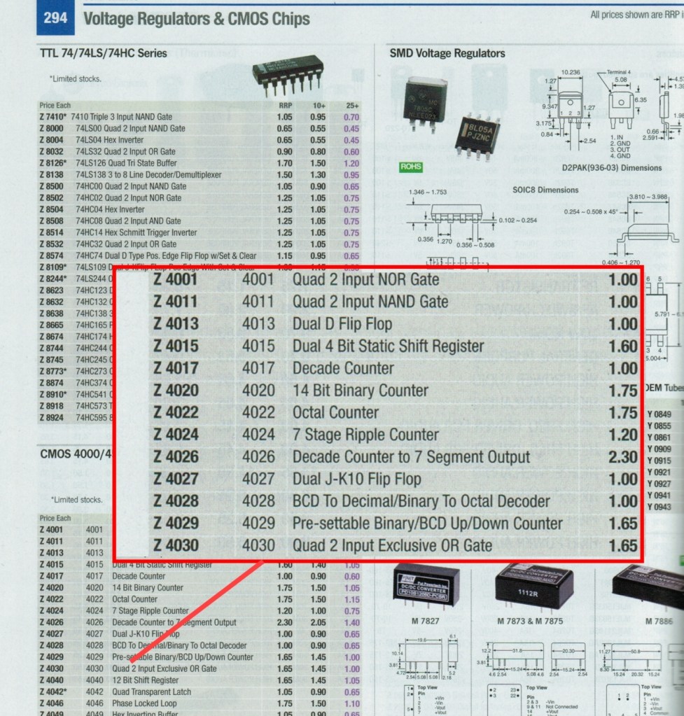
Here is an extract from the National Semiconductor ‘Radio Shack’ data book circa 1976.

By the mid 1970’s manufacturers were producing millions of these devices for just a few cents each and it created a revolution in electronics. Each manufacturer produced phone-book style data manuals with great detail on every device in a series.
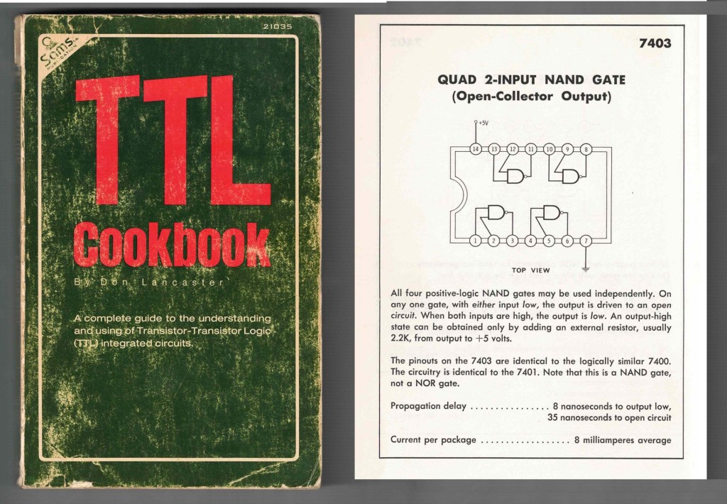
This in turn spawned simplified descriptions of these devices in books like the Don Lancaster TTL Cookbook, which became a staple handbook within every engineer’s bookcase.
For all of its flexibility there were serious limitations of the 7400 series transistor based devices. The TTL inputs could only be connected to one output unless it was ‘buffered’ by additional devices. The output stages of TTL could only drive a maximum of ten other devices. In larger, more complex logic systems this was a problem. Because of transistor junctions, the logic states were not absolute. A Logic Low state would not fall below 0.8V and a logic High could be anywhere between 3.3V and 5V. Every second device had to have its own supply filter capacitor lest its switching would affect adjacent devices.
Some designs had to be nursed with extra pullup resistors and there were small variations between manufacturers which would make some parts with the same code brand specific to make a circuit work.
There were low power variants with an ‘L’ after the 74 that had slow 10 nanosecond reaction times, but consumed less current. High power versions with a ‘H’ were faster, doubled power consumption, but would react down to 6 nanoseconds, or 50 MHz.
Despite the limitations, thousands of medium and complex designs relied upon TTL devices. This also made for some very large and difficult to service circuit boards.

The Introduction of CMOS
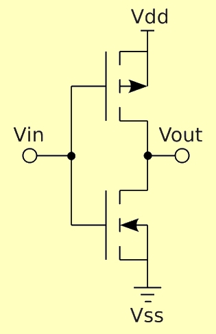
In the late 1970’s a new family of logic chips emerged. This one was based upon FET rather than bipolar transistor devices and had many advantages over the original TTL series. CMOS is short for Complimentary Metal Oxide Semiconductor. The same favourite devices that existed in TTL form were now available in the 4000 series of chips. The image below shows the arrangement of MOSFET devices internal to a 4069 chip for a single INVERTER stage.
CMOS would work on a power rail from 3 to 30 volts. Not just the fixed 5V rail. The outputs would swing from rail to rail, so that in a 5V system, the outputs would produce a wide 0 or +5V logic signal. Inputs would use a half-rail voltage as a threshold between a Low and High input signal, which was 2.5V on a 5V rail. They generated far less switching noise than TTL and it was cheap to manufacture. Engineers were fast to adopt this new technology.
The original series had a high sensitivity to static charges and could be destroyed by casual handling. This was quickly resolved by the introduction of the B series which had integral protection diodes on most inputs and outputs. Today When looking at a CMOS part on a circuit board the 4-digit 4000 code is usually followed by the letter ‘B’ to signify this protection.

4000 series devices worked their way into many radios in the 1980s, as can be seen by the logic symbols in this circuit portion of the Phillips FM321 70cm rig.

Amateur Radio home brewers used many of these devices in projects like this Squelch Impulse counter was built into an Icom IC22s that would trigger an alert if a remote station pressed their PTT five times in a row. Timing delays could be made using resistors and capacitors slowly charging into a CMOS device to count real-world events.

Component Suppliers like Australia’s Altronics would keep a good cross-section of CMOS devices for low cost project work, with many chips under a dollar each. Originally all devices were in a DIP package with standardised power rails in diagonal corners of each device.
With the introduction of the 4000 series, It was possible to dive into an unknown circuit board, look for a CMOS chip anywhere on the board, then safely measure the power rails on the diagonal pins to see if correct power is in that part of the circuit.
By the 1990’s most of these devices were also available in surface mount versions to save circuit board space. Later, from around the year 2000, powerful one-chip microprocessors became cheap and plentiful. Now, instead of engineering a logic design using basic gates, creators could simply drop in a microprocessor, program the pins and their behaviour in Assembler or C and produce the same results with fewer parts. Modifications could be carried out in software rather than re-building an entire circuit. There was a rapid decline in hard-wired logic based systems and sales demand of the devices plummeted.
Today some, but not all of these TTL and CMOS devices are still available through mainstream suppliers. There are many situations in modern designs where a problem is still being solved quickly and simply by dropping in the right 4000 series chip into a circuit. These devices will still be around for many years to come.

Some Useful links
https://toshiba.semicon-storage.com/info/docget.jsp?did=68970
