P255
Operational Amplifiers (OpAmps)
Introduction
A key building block of electronics that does not receive deserved attention is the Operational Amplifier, or OpAmp as it is usually known. Few radios would have been built in the past fifty years without some of these devices contained within their circuits. For many Amateurs these devices remain a mystery. Below is an example circuit of an antenna rotator control unit. In the centre of the circuit are three triangular devices. These are OpAmps. Without some introduction to OpAmp technology, it can be difficult to comprehend what these devices are doing here.

OpAmps in Amateur Exams
Operational Amplifiers don’t appear in the Foundation and Standard exam syllabus. The Advanced Amateur Syllabus does reference them in a limited way. The Miscellaneous section of the syllabus states ‘Simple integrated circuits (include opamps).’
While a knowledge of OpAmps is only a small part of Amateur qualifications, they are used in many circuits. A basic understanding is tremendously useful for building and servicing a wide range of equipment. Before attempting any interpretation of the above rotator circuit, we must first examine some basics.
Plenty of these devices are still in service
Fundamentally all OpAmps are similar. They are all amplifiers with two inputs and one output. One of the inputs is labelled with a minus ‘-‘ sign and the other a plus ‘+’ sign, which means that it has an Inverting Input and a non-inverting input. The trick is that the gain of the amplifier is fully adjustable by changing values of the resistors near these devices. It allows them to be used in a wide range of situations.
There are a lot of different OpAmp part numbers. In early days it was very common to see OpAmp circuits with split power rails where it may require a +15V and a -15V supply to work. Now we see that most popular devices work from a single power rail, with outputs capable of driving to the full extent of those rails.
One of the most ubiquitious devices is the LM741 OpAmp. Millions have been made since the 1970’s and any Amateur active in the 1960’s, 70’s and 80’s will have a more than few of these devices in their junk boxes.

Over the next four case studies we shall introduce some of the ways that OpAmps can be used.
Case 1 – Unity Gain
You have a signal, it varies between 1 and 12 Volts, but it is very weak. Whenever you try to use the signal for an application, it is affected by any loading of the circuit. This is a job for an OpAmp set to Unity Gain. This means whatever voltage is fed into the amplifier comes back out of it, but because of the high input impedance of the OpAmp, any loading on the signal output will have little affect upon the signal source.

By providing direct feedback from the output to the Inverting Input, gain of the device is fixed to x1.
Case 2 – 2x Gain
In this situation picture a microprocessor with a 0-5 Volt analog output that we want to use to control the speed of a variable speed fan. However, the fan has a 0-10V input control, meaning that the microprocessor can only drive the fan to 5V half-speed.
To correctly drive the fan we require a method to precisely double the output voltage of the microprocessor, so that 1 volt in has 2 volts out. 3 volts in makes 6V out and the maximum 5V from the microprocessor will drive a full 10V output.
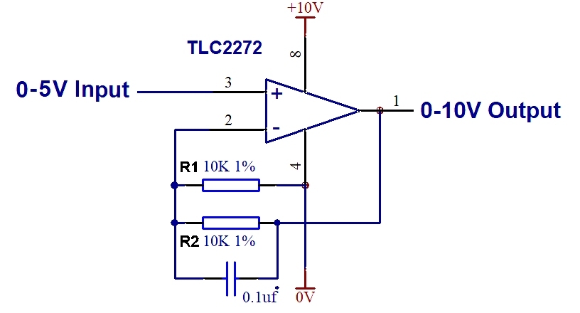
The above circuit example uses the TLC2272 device. It has two resistors of the same value which divides the output signal by two and feeds the result into the inverting input. This causes the device to have a precise x2 gain on its non-inverting input.
By adjusting the ratios of the two resistors, any fixed gain level can be created using the formula: GAIN = R1+R2 / R1
The small capacitor does not affect gain, but helps to filter out any noise that may come out of the microprocessor that feeds the circuit.
Case 3 – An Inverting Amplifier.
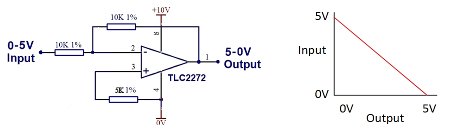
Consider a situation where we have a device with an input that is used to set the speed of an electric motor, where 0V = zero speed and +5V = maximum speed. However the signal that we have available from a manual control is reversed so that 0V = Maximum speed and +5V = zero speed. To drive the motor correctly we need a simple way to invert the source signal.
In the example below we direct the signal to the Inverting input and set the gain of the amplifier for x1 gain. Just one OpAmp device and a few resistors can easily invert the source signal and make it compatible with the motor driver. The result is a nice, linear signal conversion. A 0V input produces a 5 volt output. A 1 volt input would produce a 4 volt output. A 5V input would produce a 0V output.
Case 4 – Comparing signals for a Thermostat Fan
This case is a more sophisticated application for an OpAmp. In this example we want to control a cooling fan where a temperature sensor will activate the fan when the temperature reaches an adjustable threshold. It must turn the fan off again when the temperature falls. We utilise the signal comparison or comparator features of an OpAmp to achieve this effect.
The non-inverting (+) input of the OpAmp connects to a potentiometer P1 that can deliver an adjustable voltage, (limited in scope by R2 and R3). The temperature sensor and R1 form a voltage divider which delivers a voltage to the Inverting ( – ) input of the OpAmp proportional to the temperature of the equipment we need to cool.
In this configuration, the device has no feedback resistor from the output, so it assumes a very high gain. The output will always be in either an ON or OFF state.
When the temperature present produces a sensor voltage that is lower than the trimmer resistor voltage, the output of the device is close to zero volts and the transistor & switching relay remain OFF. As soon as the temperature has risen sufficiently for the ( + ) signal to exceed the ( – ) signal the output of the OpAmp will flip to a high 12V volt state and activate the relay contact, which in turn will activate the cooling fan. When the equipment cools and the thermistor voltage falls below the trimmer resistor reference voltage, the output of the OpAmp will flip back to the OFF state and deactivate the fan.

In Summary:
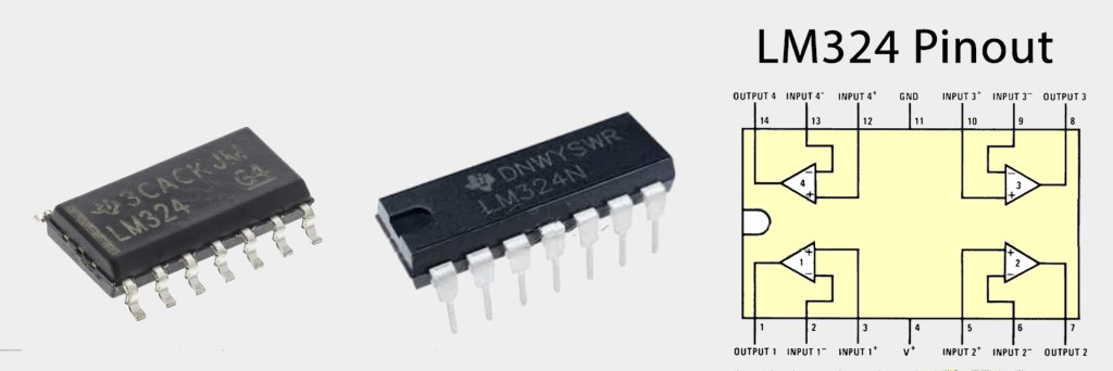
The power of OpAmps in electronic circuits are extensive. Stages working in concert in different configurations can perform a lot of useful work. Multi-device OpAmp chips are common, such as this LM324 which has four independent OpAmp stages in a 14 pin IC.
It is true that in modern circuits many of the analog effects of an OpAmp can be replicated in software by a small microprocessor and digitisation of signals ultimately reduces the total component count in a circuit. However there are times where it is not convenient or appropriate to program a chip and the placement of a cheap OpAmp device will neatly solve a design problem. Regardless, there will always be plenty of legacy circuits in the field that utilise OpAmps and these will still need to be serviced.
In this page we have only touched on basic applications of OpAmp devices. They can also be designed as filter circuits with controllable attenuation and bandwidth. There is a lot of mathematics that can be applied to OpAmp modelling which has not been covered here. Many books have been written on the topic where explanations provide far greater detail than this simple introduction.

Before leaving this introduction, we return to the initial circuit of the antenna rotator at the top of the page. Its circuit is employs combinations of the case examples we have featured. The first two stages (right) condition signals from the potentiometer high up in the rotator and a second antenna position knob in the control box. The third stage functions as a comparator, performing a similar task to our thermostat circuit in Case 4.
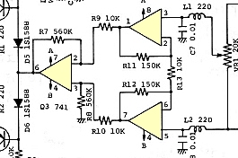
When the position knob in the control box is turned to point at a new direction, the OpAmp comparator stage will detect that there is a mismatch between the two inputs and will instruct the rotator motor up the mast to turn in an appropriate direction until the match is restored and the antenna comes to rest pointing in the selected direction. A second motor is moving a position dial for operator feedback of direction.
This type of design was very common for many years and demonstrates nicely how a single chip with multiple OpAmps can perform a complex, practical task.
Useful Links on OpAmps:
What is an Operational Amplifier?
https://web.physics.utah.edu/~jui/3620/y2009m02d03/741.html
Op-Amp cookbook for beginners:
https://www.codrey.com/electronics/741-op-amp-cookbook-for-beginners-v1/
Hackatronic tutorial on Op Amps:
https://www.hackatronic.com/op-amp-ic-741-pin-diagram-working-and-applications/
A YouTube clip which discusses OpAmps:
https://www.youtube.com/watch?v=kbVqTMy8HMg
A YouTube clip by EV Blog discusses OpAmps:
