P256
Working with Surface Mount Components
Electronics has passed through several revolutions. One such change has been the steady miniaturisation of components. The standard parts widely used in the 70’s and 80’s became smaller. Industry progressively phased out the need for components to be passed through holes in circuit boards and now place them on individual layers.
Circuit board manufacturing quality has also progressed. What was once considered to be high-end fabrication standards have now become routine
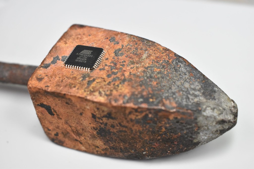
Amateur Radio as a hobby has been largely unprepared for this change. Amateur exams still contain questions on resistor colour codes, even though modern manufacturing rarely uses this convention. Unfortunately, there is very little advice in Amateur Radio education that prepares candidates for what they will encounter when the cover is removed from any modern radio. Sometimes described as ‘electronic sand’, Surface Mounted Device (SMD) components are tiny, closely spaced and often unidentified.
Even when a circuit diagram is available, it can be quite difficult to reconcile its schematic with the physical layout of a surface mount part circuit board..

In the quest to make products smaller, common compromises have been made in three key aspects of electronic engineering.
Heat: The tiny surface mount parts have low surface area and poor scope for heat dissipation. We often see products which are fine in cool weather, but under heavy loads or hot days, equipment will fail. SMD
devices can literally slide off the board when they become sufficiently hot. By contrast, traditional through-hole fabrication is far more thermally robust because of the larger surface area and pigtail connections circuit boards.
Flex & Vibration: The traditional through-hole-mounted parts in circuit boards are quite tough, particularly with through-hole plating where the solder can literally fill the hole and anchor parts to both sides of a board. The copper pigtails on through-hole parts are able to flex a little between the component core and the supporting pcb. This architecture makes for tougher electronics, which is essential in the fields of automotive, marine and aviation technology.
By contrast, modules containing many surface mount devices will have a low tolerance for physical trauma. Lacking copper pigtails, parts are hard-bonded to one side of a circuit board panel. Any twist, bend or extreme vibration can put tiny cracks through resistors and capacitors, resulting in unstable operation or complete failure. The task of locating intermittent faults on surface mount modules is very difficult. All too often, entire boards must be discarded. An entire product may have to be written off because of a single cracked resistor ‘somewhere’ on a pcb, even though the offending part may be worth less than a cent.
Flashover: Any circuit board assembly that is certified for mains operation should be engineered with appropriate spacing between parts which convey high voltage potentials. This protocol is termed ‘creepage and clearance’.
In the quest to make products smaller, designers frequently take short cuts.
Equipment may be great in a clean and dry environment. A little humidity combined with dust and high voltage potentials can cause catastrophic flashover and even fire

Generally speaking, the older through-hole pcb modules, with bigger track spacing and wider track widths are more able to handle high current with less chance of breakdown and arcing. Surface mount connectors on the edge of products, such as charging and audio sockets, only require a small knock to break away from the pcb material. A very common point of failure.
Of course, all of the above problems can be overcome if surface mount board designs have been properly engineered. PCB’s can be mounted at multiple anchor points and perhaps sealed in epoxy resin or other environmental coating. It is when these precautions are not taken that consumer products are unnecessarily fragile.
Most Amateur Radio operators will have a reasonable understanding of electronic basics, but many are not prepared for the reality of SMD miniaturisation and avoid working with it. Unfortunately this reluctance is compounded by the average age of Amateur experimenters, where sharpness of eyesight and steadiness of hand tends not to improve over time.
The art of working with surface mount devices involves three distinct areas of discipline:
- Recognising components
- Manipulating components
- Soldering and de-soldering techniques
There are further challenges not discussed here, such as designing pcb’s with SMD parts and methods for fault-finding SMD assemblies.
A modern electronics workshop carries many specialised tools for working with SMD parts and the staff within such workshops will have developed expertise in how to use them. Even then, the work can be difficult.
Most amateurs will have the limited SMD armoury of: a basic soldering station, a magnifying glass, a pair of tweezers and not much else. There will be many instances where this is simply not enough. This article is not intended to turn experimenters into engineers and there are other valid techniques in use beyond what is described here. The methods discussed should serve as a useful guide for anyone attempting to work with SMD components for the first time.
Recognising Components
Within the vast realm of available surface mount devices, IC pin spacings will vary between fine, very fine and microscopic, depending upon the intended density of design. Discrete SMD components also come in different families of size. These categories of case style use ‘identifier codes’ which correspond with the height and width of each part.
Resistor values & sizes
Resistors are usually marked with a 4 digit code, with the rightmost digit representing how many zero’s to add to the first three digits.
In the adjacent example we see a device labelled 4702, which equates to 470 plus two zeros, or 47000 ohms, commonly referred to as 47K.
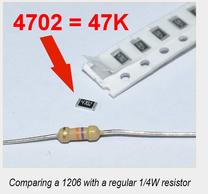
SMD resistors usually come packaged within a section of paper tape, or an entire reel. A thin film must be peeled back to release the part from the strip.
Manually un-packing these parts is best done in the bottom of a shallow white-plastic tray, as the parts are very easily lost on the bench or a carpeted floor.
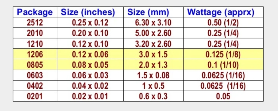
The table below shows the dimensions of common resistor packages, with the two highlighted rows being the most frequently used styles. There is a correlation between the package code and the device dimensions (in inches). For example the 1206 device is 0.12” long and 0.06” wide.
This page has been an extract from the 2021 April/June edition of QTC.
Read the full article here: https://qtcmag.com/books/zupu/#p=40
Some useful SMD links
https://wiki.restarters.net/Surface_mount_and_micro_soldering
