P260
RS232 Serial Communications
Serial communications using ASCII characters and controls have been around now for many years. Despite advances in USB and Bluetooth interfaces, there is still a strong role for simple serial communications when using micro’s to communicate with the outside world. If you need to send a few items of information to a micro or host PC via hard wire, RF modules or Infrared LED, then this page may assist.
ASCII CHARACTERS
The ASCII code is an abbreviation for the American Standard Code for Information Interchange. It has now been around for a long time, devised by Bob Bemer of IBM in the 1950’s. Put simply, eight bits (one byte) in binary can provide 256 combinations of ‘one’s and ‘zero’s. To each of the 256 combinations various printable characters and control codes have been allocated.
This table shows Decimal ASCII numbers, 0 to 127, plus octal and Hexadecimal equivalents, followed by the matching ASCII character.
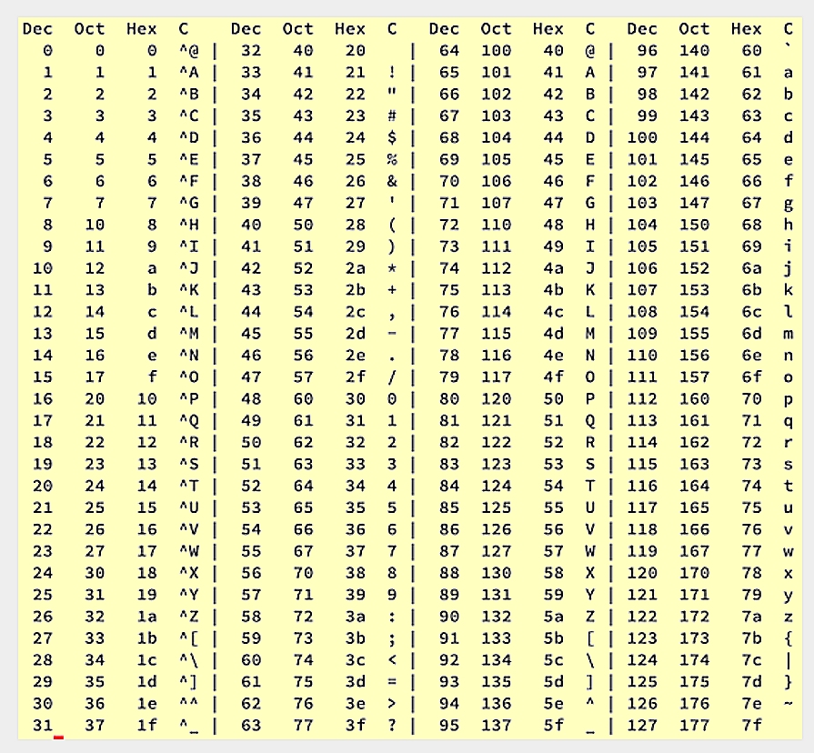
A unique number has been allocated to letters A to Z in both Upper and Lower case.
There are text numbers 0 to 9, special characters !@#$%^&*() etc. and many specialist control codes. Some of these control codes are largely obsolete commands dedicated to old TELIX services and line printers, but most of them still hold relevance whenever computer information is being sent as plain text.
For example the character 13 is called (CR) for ‘CARRIAGE RETURN’, which is now associated with the pressing of the ENTER key on a keyboard and character 27 is (ESC) the ESCAPE button.
On a PC keyboard all of these characters can be generated via the numeric keypad. If a user holds down the <Alt> button on any keyboard, (say within a word processor program) then tap in the digits ‘7’ and ‘5’ on the numeric keypad on the right hand end of the keyboard. When the <Alt> key is released the letter ‘K’ should appear, because the decimal character for an uppercase ‘K is 75. This is a useful trick for generating all sorts of characters.
Regardless of this, it is possible to use any Ascii character to perform whatever task is allocated to it. The microprocessor inside will not care what you have told it to send.
SERIAL DATA CONCEPT
The old ‘Parallel’ printers used a 36 wire cable to print things from a PC. The 8 bit data was sent via 8 wires simultaneously, which is a fast but inconvenient method if you also want to send data via telephone modem or any other 2 wire circuit. With Serial communications the each byte must be sent as a synchronised series of high and low bits.
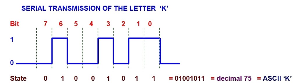
When this information is sent along a single wire, or out of a single pin of a chip, each logic state of ‘1’ or ‘0’ exists for a short time. if this data is sent with sorter pulse durations, the bits-per-second or ‘BAUD” rate increases. There are quite a number of standard transmission speeds in use. Most PC serial ports (and our AVR device) will support 300 baud through to 115,000 baud speeds, with 1200 and 9600 baud being the most common of these speeds.
It is simple to calculate the duration of the smallest data element (one eighth of a byte) by dividing the baud rate into 1. Therefore if the above example for the letter k was being sent at 9600 baud, the duration of each bit would be 104 microseconds.
(The modern USB port is really a high-speed serial port, with the USB2.0 standard reaching 460,000,000 bits per second, a speed that has made large USB hard drives and memory sticks feasible.)
There are some extra bits that are usually sent in conventional data transmissions called stop bits and parity bits. The most common configuration is N, 8, 1 meaning no parity, 8 data bits and 1 stop bit. All sorts of variations are in use and the AVR can support most of them.
THE UART (USART)
In the world of microprocessors and Arduino modules it is possible to write a program that will send and receive serial data pulses where every bit element is generated by the programmers code, all of which is a lot of hard work. Indeed many systems still do this, but it chews up a lot of prime microprocessor resources to manage this, so the UART was invented. The UART is a dedicated chip (or part of a chip) for sending and receiving serial data, to free the microprocessor for more important tasks. UART stands for Universal Asynchronous Receiver Transmitter. These are really neat and manage the entire send-receive operation for us. The modern Arduino module has a port with a very advanced UART module inside it called an EUSART for Extended Universal Synchronous and Asynchronous serial Receiver and Transmitter for performing many serial communications tasks. Here we shall simply refer to it as the USART or Serial Port because life is too short to use the full name every time.
As far as the programmer is concerned, the serial port exists as a collection of memory registers. First you set up registers to establish some options and baud rates. If data is being sent, simply load a Transmit register with a byte of data at frequent intervals and everything is managed automatically. Serial data then comes out of the USART port upon demand.
While this document does not cover receiving of serial data by a microprocessor in great detail, what normally happens is that a byte of data arrives at as Serial Port input and is held in a buffer register. This generates an interrupt as well, so that the microprocessor is alerted to incoming data and says ‘Hey, a byte has just arrived. Are you going to use it? Because more bytes are probably on their way…’ The programmer must then write the appropriate routines to empty out the receive buffer and figure out what to do with the information.
RS232 STANDARD
RS232 is a set of conventions for sending serial data. The data that comes out of a micro is 0 to +5V logic. This is not suitable for sending over long wire lengths because the capacitance between the conductors in the cable charge up to the peak DC value and distort high speed serial data. By convention, any serial comms within a circuit board boundary uses 0-5V logic and anything communicating via conventional RS232 cables has the logic converted to a +/-9V logic that alternates data polarity with each bit to overcome cable capacitance.
The way that the RS232 standard developed has meant that all the line driver chips have inverting outputs which flip the data pulses upside down as well as boosting them.
To compensate for this, the serial output from the UART/USART within most micro’s is normally upside down. That is the quiet state is a ‘1’ and it pulses to a ‘0’ with TX data.
The image below shows a screen capture of data from the SM255 module both before and after the RS232 output driver chip called a MAX232. The upper trace (channel 1) comes directly from the AVR micro and shows inverted 0-5V logic. The lower trace (channel 2) shows the +/- 9V logic that is sent to the standard DB9 PC serial port connector.
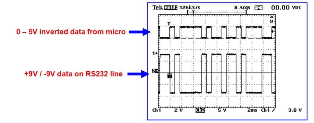
The MAX232 (or the DS232 equivalent) is an excellent device to use for serial comms. It has three transmit drivers and 3 receive buffers. The chip works from a single +5V rail, but by using four 10uf capacitors it can synthesize the necessary +/- 9V rails for three true RS232 outputs. The three receive lines are equipped to accept a +/-9V signal and will translate it back to the inverted 0-5V logic required for a UART or micro device.
TRANSMITTING VIA INFRARED
Occasionally a project may be constructed that will need to send serial data using cordless means. Infrared transmission is reasonably easy to do. Infrared LEDs are cheap and can be connected directly to microprocessor serial ports (via a small resistor) to generate a data transmission. Note that if the transmission range is reasonably short, almost any LED can be used to send data, but the proper infrared LEDs have a narrow angle of radiation which help to increase range.
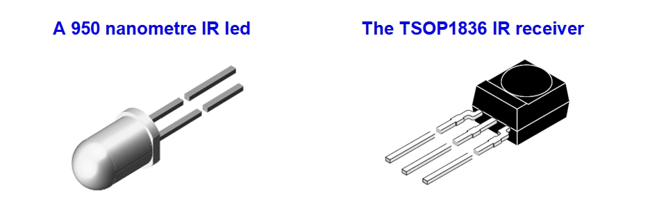
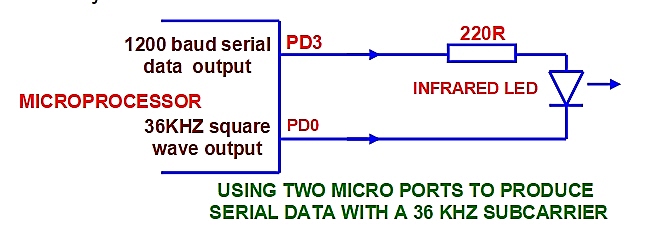
The best way to receive a transmission is with a special IR receiver device such as the TSOP1836 or similar device. These are 5V powered and produce the necessary inverted serial data signals to feed the receive line in the serial port of a micro. One important aspect is that they require a sub-carrier (36KHz square wave) to be superimposed on the infrared transmission in order to provide greater immunity to daylight interference.
This can be done by using one of the system timers in the micro to produce a 36KHz square wave and feed the led between the two ports so that the LED is radiating a blend of the two signals. For superior drive and better IR range an additional transistor or two will help improve the output reliability
SENDING DATA WITH RF MODULES
A simple RF link for serial data transmissions can be made using readily available LIPD modules on UHF. For under ten dollars each, transmit and receive modules can be purchased that will connect directly to a micro. A one- milliwatt transmitter will provide a range of around 30 metres on 433.920MHz. The receiver modules (shown below) require little or no tuning and will support AM data transmissions of up to 4800 baud.
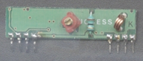
Each module requires an antenna wire which can be achieved with a quarter wavelength of 1mm enamelled copper wire. If space is tight, an antenna track can be etched around the perimeter of the circuit board, but this introduces some losses that will reduce the range somewhat.
ERROR CHECKING
When sending data it is reasonable to expect that the information will arrive intact, but it is wise to work on the basis of some corruption taking place. If a data string sent by RF module had a control byte to turn a garden tap on or off and the next byte to activate a dog feeder function, then a missing byte earlier in the TX string could shift all the functions by one byte, resulting in an obese or drowned dog. There are a coupe of strategies that can improve system reliability.
End-Of-String Characters
It is a good plan to send a couple of standard characters at the end of a string to simplify the processing of commands at the receiving end. A common method is to end a data string with a Carriage Return and Line Feed character (ASCII 13 and 10) The receiving program looks for these two characters in immediate succession, then assumes that the preceding 11 bytes are the relevant data bytes for processing. This is ok for a hardwire system, but not good enough for Infrared or RF systems.
Matching data strings
One accurate transmission method is to send the critical data three times in quick succession. At the receiving end each string is compared with the other adjacent two strings and action will be taken only if two or more of the strings match. This works well and provides a certain amount of redundancy, but there needs to be some careful programming at the receive end to make all of the necessary comparisons.
Traditional Checksum Techniques
This is not foolproof but it would be a minimum requirement for important control functions and is fairly easy to implement. Essentially all the values of all of the bytes are added up into a large number, which is placed at the end of the data string. At the receiving end the bytes are also added up and if the total value does not match the end bytes, the string is discarded.
Here is an example:
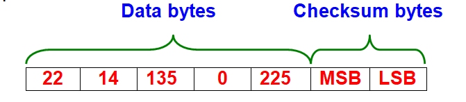
Get the micro to add up the value of the first five bytes here in a 16 bit register like the ‘Z’ register. Place the lower byte of the Z register into LSB (least significant byte) and the upper byte of the Z register into the MSB (most significant byte), then send the entire seven bytes to the serial port. The data bytes 22 + 14 + 135 + 0 + 225 add up to 396 or 00000001 10001100 in binary, so that the MSB would contain ‘1’ and the LSB would contain ‘140’.
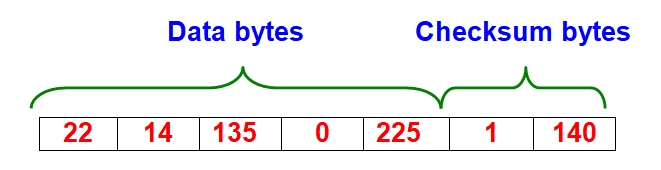
At the receiving end, seven bytes are assessed the same way. The first five are added up and the total of them (396) should match the value in the checksum bytes. If they do not match then the data is corrupt somewhere. It is better to wait for the next transmission.
UNIQUE IDENTITY FORMATS
If the serial transmission is via a wireless medium then identity of the transmission is important. It is unwise to use transmitted control signals on equipment such as garage doors unless the transmission incorporates a unique code. Reserving just two bytes as an I.D. byte is usually sufficient for most applications as together they permit 256 x 256 alternatives, which equates to 65,536 possible combinations.
A common approach is to incorporate ‘learn’ modes within a system where a random number is stored in a transmitter device and under controlled conditions it is sent to the host system to be stored in a non-volatile memory. Valid actions are taken only if the transmitted and stored I.D. codes match.
More elaborate systems of synchronised code hopping have become commonplace, but these can be quite complex at the design level.
