P3
Note: This Advanced Syllabus is in a format to match internationally recognised conventions for the higher level Amateur Radio qualification. Unlike the Foundation and Standard syllabus, this Advanced Syllabus does not include content on Australian Regulations and procedures, or details of a Practical Assessment. It is assumed that the candidate will attempt the Regulations and Practical assessments as a separate exam or they have already met that requirement from successful attainment of the Foundation or Standard qualification.
ACMA recognition certificate (Advanced)
Syllabus and examination information
FEBRUARY 2024
This document describes the syllabus for the ACMA recognition certificate (Advanced) for amateur radio in Australia.
The ACMA recognition certificate (Advanced) is the advanced qualification for amateur radio in Australia. This syllabus has been produced for the guidance of the administrations so that they may prepare their national amateur radio examinations for the CEPT Harmonised Amateur Radio Examination Certificate (HAREC).
The ACMA Advanced recognition certificate allows people to operate an amateur station only on advanced frequencies, in accordance with the relevant conditions set out in the Radiocommunications (Amateur Stations) Class Licence 2023
Notes
The purpose of the examination is to set a reasonable level of knowledge required for candidate radio amateurs wishing to obtain a certificate for operating amateur stations.
The scope of the examination is limited to subjects relevant to tests and experiments with, and operation of, amateur stations. These include circuits and their diagrams. Questions may relate to circuits using both integrated circuits and discreet components.
a) Where quantities are referred to, candidates should know the units in which these quantities are expressed, as well as the generally used multiples and sub-multiples of these units.
b) Candidates must be familiar with the compound of the symbols.
c) Candidates must know the following mathematical concepts and operations:
- adding, subtracting, multiplying and dividing
- fractions
- powers of ten, exponentials, logarithms
- squaring
- square roots
- inverse values
- interpretation of linear and non-linear graphs
- binary number system.
d) Candidates must be familiar with the formulae used in this syllabus and be able to transpose them.
ACMA recognition certificate (Advanced) and HAREC – syllabus summary
Technical content
1. Electrical, electromagnetic and Radio Theory
1.1 Conductivity
1.2 Sources of electricity
1.3 Electric field
1.4 Magnetic field
1.5 Electromagnetic field
1.6 Sinusoidal signals
1.7 Non-sinusoidal signals, noise
1.8 Modulated signals
1.9 Power and energy
1.10 Digital signal processing (DSP)
2. Components
2.1 Resistor
2.2 Capacitor
2.3 Coil
2.4 Transformers application and use
2.5 Diode
2.6 Transistor
2.7 Miscellaneous
3. Circuits
3.1 Combination of components
3.2 Filter
3.3 Power supply
3.4 Amplifier
3.5 Detector
3.6 Oscillator
3.7 Phase Locked Loop [PLL]
3.8 Discrete Time Signals and Systems (DSP systems
4. Receivers
4.1 Types
4.2 Block diagrams
4.3 Operation and function of the following stages
4.4 Receiver characteristics
5. Transmitters
5.1 Types
5.2 Block Diagrams
5.3 Operation and function of the following stages
5.4 Transmitter Characteristics
6. Antennas and Transmission Lines
6.1 Antenna types
6.2 Antenna characteristics
6.3 Transmission lines
7. Propagation
8. Measurements
8.1 Making Measurements
8.2 Measuring Instruments
9. Interference and Immunity
9.1 Interference in electronic equipment
9.2 Cause of interference in electronic equipment
9.3 Measures against interference.
10. Safety
National and international operating rules and procedures
- Phonetic alphabet Q-code
- Operational abbreviations
- International distress signs, emergency traffic and natural disaster communication call signs
- IARU band plans
- Social responsibility and operating procedures.
National and international regulations relevant to the amateur service and amateur satellite service
- ITU Radio Regulations
- CEPT Regulations
- National laws, regulations and licence conditions.
ACMA recognition certificate (Advanced) and HAREC – detailed syllabus
Note: The formulas shown here use the symbol E to represent Voltage. E is an abbreviation of Electro Motive Force (EMF). Many educational documents use V for Voltage instead. For the purposes of this assessment, the symbol E and V are interchangeable.
Technical content
Chapter 1 Electrical, Electromagnetic and Radio Theory
1.1 Conductivity
- Conductor, semiconductor and insulator
- Current, voltage and resistance
- The units ampere, volt and ohm
- Ohm’s Law [E = I ⋅ R]
- Kirchhoff’s Laws
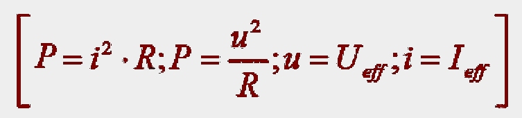
- Electric power [P = E ⋅ I ]
- The unit watt
- Electric energy [W = P ⋅ t]
- The capacity of a battery [ampere-hour].
1.2 Sources of electricity
- Voltage source, source voltage [EMF], short circuit current, internal resistance and terminal voltage
- Series and parallel connection of voltage sources.
1.3 Electric field
- Electric field strength
- The unit volt/meter
- Shielding of electric fields.
1.4 Magnetic field
- Magnetic field surrounding live conductor
- Shielding of magnetic fields.
- 1.5 Electromagnetic field
- Radio waves as electromagnetic waves
- Propagation velocity and its relation to frequency and wavelength [v = f ⋅ λ]
- Polarisation.
1.6 Sinusoidal signals
- The graphic representation in time
- Instantaneous value, amplitude [Emax], effective [RMS] value and average value
- Period and duration of period
- Frequency
- The unit hertz
- Phase difference.
1.7 Non-sinusoidal signals
- Audio signals
- Square wave
- The graphic representation in time
- D.C. voltage component, fundamental wave and higher harmonics
- Noise [PN = kTB] (receiver thermal noise, band noise, noise density, noise power in receiver bandwidth).
1.8 Modulated signals
- CW
- Amplitude modulation
- Phase modulation, frequency modulation and single-sideband modulation
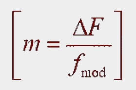
- Frequency deviation and modulation index
- Carrier, sidebands and bandwidth
- Waveforms of CW, AM, SSB and FM signals (graphical presentation)
- Spectrum of CW, AM and SSB signals (graphical presentation)
- Digital modulations: FSK, 2-PSK, 4-PSK, QAM
- Digital modulation: bit rate, symbol rate (Baud rate) and bandwidth
- CRC and retransmissions (e.g. packet radio), forward error correction (e.g. Amtor FEC).
1.9 Power and energy
- The power of sinusoidal signals
- Power ratios corresponding to the following dB values: 0 dB, 3 dB, 6 dB, 10 dB and 20 dB [both positive and negative]
- The input/output power ratio in dB of series-connected amplifiers and/or attenuators
- Matching [maximum power transfer]
- The relation between power input and output and efficiency

- Peak Envelope Power [p.e.p.].
1.10 Digital Signal Processing (DSP)
- sampling and quantisation
- minimum sampling rate (Nyquist frequency)
- convolution (time domain / frequency domain, graphical presentation)
- anti-aliasing filtering, reconstruction filtering
- ADC / DAC.
Chapter 2 Components
2.1 Resistor
- The unit ohm
- Resistance
- Current/voltage characteristic
- Power dissipation.
2.2 Capacitor
- Capacitance
- The unit farad
- The relation between capacitance, dimensions and dielectric. (Qualitative treatment only)
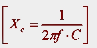
- The reactance
- Phase relation between voltage and current.
2.3 Coil
- Self-inductance
- The unit henry
- The effect of number of turns, diameter, length and core material on inductance. (Qualitative treatment only)
- The reactance

- Phase relation between current and voltage
- Q-factor.
2.4 Transformers application and use
- Ideal transformer
- The relation between turn ratio and:
- voltage ratio
- current ratio
- impedance ratio.
- Transformers.
2.5 Diode
- Use and application of diodes:
- Rectifier diode, zener diode, LED [light-emitting diode], voltage-variable and capacitor [varicap]
- Reverse voltage and leakage current.
2.6 Transistor
- PNP- and NPN-transistors
- Amplification factor
- Field effect vs. bipolar transistor (voltage vs. current driven)
- The transistor in the:
- common emitter circuit
- common base [gate] circuit
- common collector [drain] circuit
- input and output impedances of the above circuits.
2.7 Miscellaneous
- Simple thermionic device [valve]
- Voltages and impedances in high power valve stages, impedance transformation
- Simple integrated circuits (include opamps).
Chapter 3 Circuits
3.1 Combination of components
- Series and parallel circuits of resistors, coils, capacitors, transformers and diodes
- Current and voltage in these circuits
- Behaviour of real (non-ideal) resistor, capacitor and inductors at high frequencies.
3.2 Filter
- Series-tuned and parallel-tuned circuit
- Impedance
- Frequency characteristic

- Resonance frequency
- Quality factor of a tuned circuit

- Bandwidth
- Band-pass filter
- Low-pass, high-pass, band-pass and band-stop filters composed of passive elements
- Frequency response
- Pi filter and T filter
- Quartz crystal
- Effects due to real (=non-ideal) components
- Digital filters (see sections 1.10 and 3.8).
3.3 Power supply
- Circuits for half-wave and full-wave rectification and the Bridge rectifier
- Smoothing circuits
- Stabilisation circuits in low voltage supplies
- Switching mode power supplies, isolation and EMC.
3.4 Amplifier
- LF and HF amplifiers
- Gain
- Amplitude/frequency characteristic and bandwidth (broadband vs. tuned stages)
- Class A, A/B, B and C biasing
- Harmonic and intermodulation distortion, overdriving amplifier stages.
3.5 Detector
- AM detectors (envelope detectors)
- Diode detector
- Product detectors and beat oscillators
- FM detectors.
3.6 Oscillator
- Feedback (intentional and unintentional oscillations)
- Factors affecting frequency and frequency stability conditions necessary for oscillation
- LC oscillator
- Crystal oscillator, overtone oscillator
- Voltage controlled oscillator (VCO)
- Phase noise.
3.7 Phase Locked Loop [PLL]
- Control loop with phase comparator circuit
- Frequency synthesis with a programmable divider in the feedback loop.
3.8 Digital signal processing (DSP systems)
- FIR and IIR filter topologies
- Fourier transformation (DFT FFT, graphical presentation)
- Direct digital synthesis.
Chapter 4 Receivers
4.1 Types
- Single and double superheterodyne receiver
- Direct conversion receivers.
4.2 Block diagrams
- CW receiver [A1A]
- AM receiver [A3E]
- SSB receiver for suppressed carrier telephony [J3E]
- FM receiver [F3E].
4.3 Operation and function of the following stages (Block diagram treatment only)
- HF amplifier [with tuned or fixed band pass]
- Oscillator [fixed and variable]
- Mixer
- Intermediate frequency amplifier
- Limiter
- Detector, including product detector
- Audio amplifier
- Automatic gain control
- S meter
- Squelch.
4.4 Receiver characteristics (simple description treatment)
- Adjacent-channel
- Selectivity
- Sensitivity, receiver noise, noise figure
- Stability
- Image frequency
- Desensitisation / blocking
- Intermodulation cross modulation
- Reciprocal mixing [phase noise].
Chapter 5 Transmitters
5.1 Types
- Transmitter with or without frequency translation.
5.2 Block diagrams
- CW transmitter [A1A]
- SSB transmitter with suppressed carrier telephony [J3E]
- FM transmitter with the audio signal modulating the VCO of the PLL [F3E].
5.3 Operation and functions of the following stages (simple description and block diagram)
- Mixer
- Oscillator
- Buffer
- Driver
- Frequency multiplier
- Power amplifier
- Output matching
- Output filter
- Frequency modulator
- SSB modulator
- Phase modulator
- Crystal filter.
5.4 Transmitter characteristics (simple description)
- Frequency stability
- RF bandwidth
- Sidebands
- Audio-frequency range
- Non-linearity [harmonic and intermodulation distortion]
- Output impedance
- Output power
- Efficiency
- Frequency deviation
- Modulation index
- CW key clicks and chirps
- SSB overmodulation and splatter (agreed)
- Spurious RF radiations (agreed)
- Cabinet radiations
- Phase noise.
Chapter 6 Antennas and Transmission Lines
6.1 Antenna types
- Centre-fed half-wave antenna
- End-fed half-wave antenna
- Folded dipole
- Quarter-wave vertical antenna [ground plane]
- Antenna with parasitic elements [Yagi]
- Aperture antennas (Parabolic reflector, horn)
- Trap dipole.
6.2 Antenna characteristics
- Distribution of the current and voltage
- Impedance at the feed point
- Capacitive or inductive impedance of a non-resonant antenna
- Polarisation
- Antenna directivity, efficiency and gain
- Capture area
- Radiated power [ERP, EIRP]
- Front-to-back ratio
- Horizontal and vertical radiation patterns.
6.3 Transmission lines
- Parallel conductor line
- Coaxial cable
- Waveguide
- Characteristic impedance [ZO]
- Velocity factor
- Standing-wave ratio
- Losses
- Balun
- Antenna tuning units (pi and T configurations only).
Chapter 7 Propagation
- Signal attenuation, signal to noise ratio
- Line of sight propagation (free space propagation, inverse square law)
- Ionospheric layers
- Critical frequency
- Influence of the sun on the ionosphere
- Maximum Usable Frequency
- Ground wave and sky wave, angle of radiation and skip distance
- Multipath in ionospheric propagation
- Fading
- Troposphere (ducting, scattering)
- The influence of the height of antennas on the distance that can be covered [radio horizon]
- Temperature inversion
- Sporadic E-reflection
- Auroral scattering
- Meteor scatter
- Reflections from the moon
- Atmospheric noise [distant thunderstorms]
- Galactic noise
- Ground (thermal) noise.
- Propagation prediction basics (link budget):
- dominant noise source, (band noise vs. receiver noise)
- minimum signal to noise ratio
- minimum received signal power
- path loss
- antenna gains, transmission line losses
- minimum transmitter power.
Chapter 8 Measurements
8.1 Making measurements
- Measurement of:
- DC and AC voltages and currents
- Measuring errors:
- influence of frequency
- influence of waveform
- influence of internal resistance of meters.
- Resistance
- DC and RF power [average power, peak envelope power]
- Voltage standing-wave ratio
- Waveform of the envelope of an RF signal
- Frequency
- Resonant frequency.
8.2 Measuring instruments
- Making measurements using:
- Multi-range meter (digital and analog)
- RF power meter
- Reflectometer bridge (SWR meter)
- Signal generator
- Frequency counter
- Oscilloscope
- Spectrum analyser.
Chapter 9 Interference and Immunity
9.1 Interference in electronic equipment
- Blocking
- Interference with the desired signal
- Intermodulation
- Detection in audio circuits.
9.2 Cause of interference in electronic equipment
- Field strength of the transmitter
- Spurious radiation of the transmitter [parasitic radiation, harmonics]
- Undesired influence on the equipment:
- via the antenna input [aerial voltage, input selectivity]
- via other connected lines
- by direct radiation.
9.3 Measures against interference
- Measures to prevent and eliminate interference effects:
- filtering decoupling
- shielding.
Chapter 10 Safety
- High voltages and currents are dangerous
- Interlocks
- Mains supply and high voltage equipment including measuring equipment should be determined to by safe by a qualified person.
- Mains power supply:
- colour codes
- nature of the mains supply
- voltages and earthing
- Fuses, residual current detectors (RCDs) and other electrical safety devices
- General electrical safety practices
- Current electrical safety procedure and resuscitation techniques
- Battery safety
- Electromagnetic Radiation (EMR) – safe distance of people and animals from antennas.
- EMR safety and relation to power, frequency and distance from source
- Working at heights:
- safety
- qualified person
- Lightning protection and safety procedure for lightning storms.
- Safe use of headphones.
Examination Information
1. The examination comprises:
a) a multiple choice question paper of 50 questions covering theory. Questions may be drawn from all parts of the syllabus
b) a multiple choice question paper of 30 questions covering regulations
c) a practical component of operating knowledge and skills.
2. The Amateur Radio Qualification Framework provides clarification about exemptions to aspects of the examination when a candidate has obtained recognised amateur radio domestic qualifications.
3. A pass in the theory or regulations or demonstrated competence in the practical component of the examination, will remain valid until a pass in all parts of the examination is obtained.
4. The examination may be undertaken in one session or as part of a course of training. Ninety (90) minutes is allowed for the theory paper where the examination is undertaken in one session.
5. Thirty (30) minutes is allowed for the regulations paper where the examination is undertaken in one session.
6. Subject to exemptions, an ACMA recognition certificate can be given to persons who correctly answer 70% of the questions in both theory and regulations papers and demonstrate competence in all elements of the practical component of the examination.
7. Candidates may be supplied with reference materials in order to facilitate some of the assessment requirements. The materials may include look-up tables, formula sheets, diagrams, photographs, the Amateur Class Licence and Amateur LCD and other relevant radiocommunications regulations, band plans and physical examples.
Formula sheet
This formula sheet will be provided to candidates in the Advanced theory examination and may be used to answer any question.

