
P332
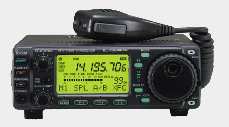
ICOM IC706MK2G
HF/VHF/UHF Transceiver – What you Need To Know
INTRODUCTION
The IC706MK2G is a clever multi-band transceiver capable of receiving from just 30KHz to 200MHz and 400 to 470MHz. It can transmit on all the amateur bands from 160 metres through to 70cm. It supports all the common modes of operation, AM FM SSB CW RTTY. Transmitter power on HF/6M is 100 Watts of SSB. On 2M FM it is 50 Watts and on 70cm 20 Watts
Note that there is a MK1 version and a MK2 version (no ‘G’) which does not support 70cm, has lower output power on some bands and did not come with digital receiver filters. The menu system on the ‘MK2G’ version described here differs significantly from the Non-G version, which is detailed in a separate WYNTK document.
It is a versatile radio, great for mobile or shack use. However there are a lot of buttons and menu settings, which makes it difficult to operate without some training and handy notes.
1. POWERING ON AND OFF
This is a simple operation. To activate the radio, briefly press the POWER button in the top Left-Hand corner of the front panel. To turn it OFF, press and hold the same button for 2 seconds.
2. BAND SELECTION
On the front Right-hand edge of the radio there are two arrow buttons labelled ‘BAND’ Pressing the upper button will step the transceiver upwards through the normal amateur bands. The lower Right-hand button will step the radio down the bands.
3. MODULATION MODE SELECTION
Mostly the radio will remember the last mode of operation used on each band, so modulation modes will usually change automatically when swapping from HF to VHF.
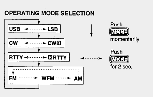
However, pressing the MODE button at the top, just to the left of the VFO knob will cycle the radio through different Mode selections of USB LSB CW RTTY FM WFM (wide FM) and AM.
4. SELECTING A VFO FREQUENCY
To use the VFO for dialling up a given frequency it is important to consider how the rig was last being used. It is possible that a couple of these steps can be skipped.
The large VFO knob could be ‘locked’ to prevent accidental rotation. Just below and to the left of the VFO knob is a button labelled LOCK with a red light next to it. If the red light is ON, then press the LOCK button to turn the lamp off and unlock the VFO control. Once you establish a contact pressing LOCK again could be good, as on a bumpy road the knob could move a bit.
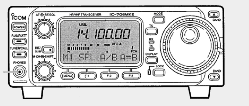
Next we must put the screen menu onto the correct level. Just below the display and to the left is the MENU button. Press this button a few times until the text on the display above the menu button says M2. To the right of the MENU button is another button labelled F-3. Pressing this button will reveal one of three selections. VFO-A, VFO-B or Frequency Memories. The rig supports two VFO controls, so select either VFO-A or VFO-B and now the main VFO knob should be capable of selecting a frequency.
5. SETTING REPEATER OFFSETS
This instruction assumes that the radio has already been pre-programmed for the correct offset amount for Australian repeaters. ie. 600KHz for 2 metres, 5MHz for 70 cm and that the FM Mode has been selected.
Just below the display, to the left is the MENU button. Press this button a few times until the text on the display above the menu button says M4. To the right of the MENU button is another button labelled F-2. Pressing this button will reveal one of three selections DUP+, DUP- or SIMPLEX (No DUP indicator)
(If a sub-audible tone (CTCSS) needs to be applied to the repeater as well, see the next section)
Next we must engage SPLIT operation to use the stored offset. Press the MENU button until M1 is shown. The letters SPL should be present above the F-1 button. Pressing the F-1 button turns the SPLIT feature on or off. The repeater split is armed when the letters SPL appear in the top right-hand corner of the display. Now when the PTT button is pressed, the display frequency will change by the offset amount. If this frequency is subsequently saved to a memory channel, then the present offset will be saved as well.
(If a sub-audible tone (CTCSS) needs to be applied to the repeater as well, see the next section)
6. SETTING SUBAUDIBLE TONES (CTCSS)
TTo add a sub-audible tone to the transmitted signal, the SET mode must be accessed. Press & hold the DISPLAY button for 2 seconds to enter this mode.
Next use the BAND UP or BAND DOWN buttons to reach setting Q6 (repeater tones). On level Q6, rotating the main VFO knob should reveal one of the many standard tone frequencies available. (GGREC repeaters use 91.5Hz) When the correct tone has been selected, press the DISPLAY button again to leave the SETTINGS area.
7. SAVING & RECALLING MEMORY FREQUENCIES
After a VFO frequency, transmission mode, have been selected, along with applicable repeater offsets and tones, it is ok to write this configuration to a memory position for future access.
SAVING TO A MEMORY
Press the MENU button until M2 is revealed on the display. Rotate the M-CH knob until a memory channel number is shown that has not previously been allocated. This is signified by the word ‘Blank’ on the display. The M-CH knob is the centre control knob just to the left of the MENU button. Now press the F1 button to write the current VFO settings to that memory position. (Note that this radio is capable of storing a title or name for each memory)
RECALLING A MEMORY
This is similar to making the VFO selection in paragraph 4. Just below the display and to the left is the MENU button. Press this button a few times until the text on the display above the menu button says M2. To the right of the MENU button is another button labelled F-3. Pressing this button will reveal one of three selections. VFO-A, VFO-B or Frequency Memories. Keep stepping through these options until Frequency Memories is shown. Stored memory selections may now be made by rotating the M-CH knob, just to the left of the MENU button.
8. ADJUSTING POWER OUTPUT
To change the transmitted power levels, the SET mode must be accessed. Press & hold the DISPLAY button for 2 seconds to enter this mode.
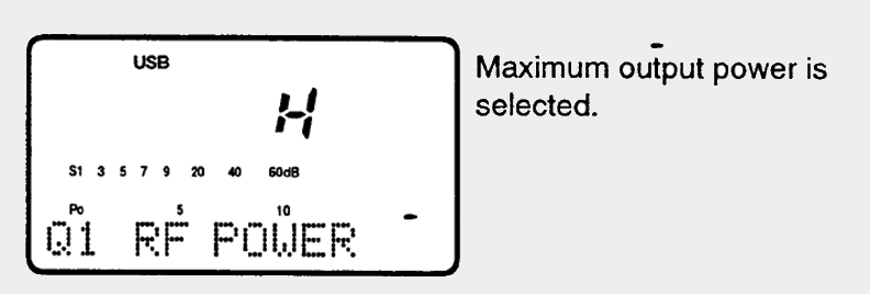
Next use the BAND UP or BAND DOWN buttons to reach setting Q1 (RF POWER).
On level Q1, rotating the main VFO knob should reveal one of eleven different transmitter power levels, from L for LOW, then settings 1 to 9, then H for HIGH. When the correct power level has been selected, press the DISPLAY button again to leave the SETTINGS area.
SPECIAL COMMENTS
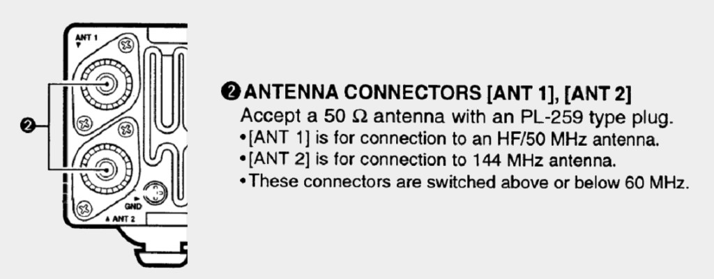
The IC706 has two SO239 antenna sockets. Be sure to connect antennas to the correct sockets. The Upper socket is for HF and 6 Metres. The Lower socket is for the 2 Metre and 70 cm bands
Download this document as a PDF

