
P336
KENWOOD TS520S
HF Transceiver – What you Need To Know
INTRODUCTION
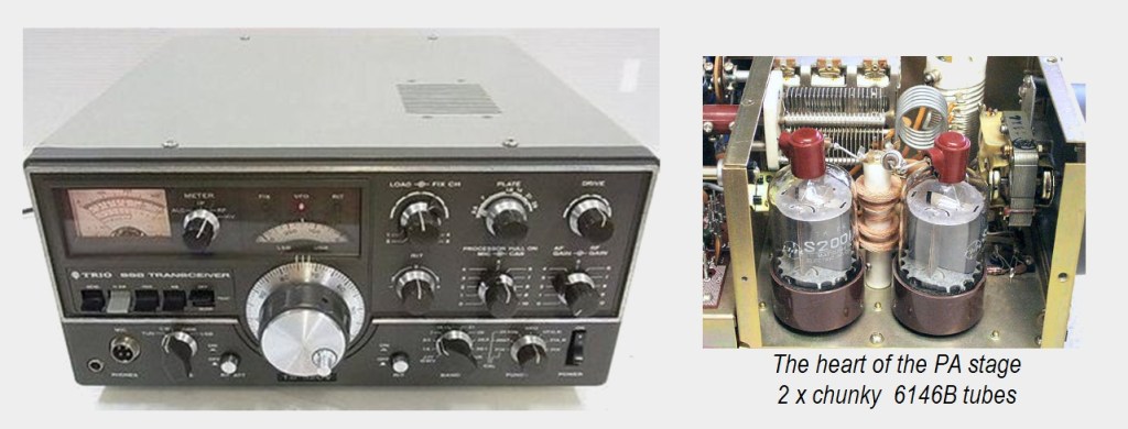
The Kenwood TS520S is one of the ubiquitous HF transceivers of the 70’s and counterpoise to the Yaesu FT101 of its day, like Ford is to Holden. It featured a solid state transceiver, except for the vacuum tube power amplifier stage – a pair of 6146 dual-tetrodes. This gave it a solid 280W PEP output on single sideband modes. The ‘S’ model was an upgrade to the original TS520 where 160 metres was added and some extra audio connection sockets. It had its own internal 240V power supply and weighed a hefty 17kg. A good performer on HF, but became dated by its lack of digital frequency readout. This was not as much of a limitation as it may seem, as any competent operator will have no problems driving its analog VFO controls.
1. POWERING ON AND OFF
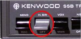
It has two power switches. There is the main ‘POWER’ switch on the bottom right corner and the vacuum tube heater switch on the centre-left labelled H.SW. This means that if you are only using the receiver for tuning around, you need not bother to warm up the vacuum tubes unnecessarily. The Power Amp filaments take about 2 minutes to reach their full operating temperature.
2. BAND SELECTION
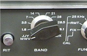
That would be the big rotary knob labelled ‘BAND’. Simply rotate it to select any of the amateur bands available on the day: 160M, 80M 40M 20M 15M 10M. (18 & 25MHZ are not available) The JJY/WWV mode allowed the operator to listen to, but not transmit on the 10MHz band
3. MODULATION MODE SELECTION
Not a lot to choose from here. Just to the right of the microphone socket is a ‘MODE’ switch that can select TUN (for tuning up) CW, USB (Upper Sideband) and LSB (Lower sideband). AM and FM transmit/receive modes were unavailable on this rig.
To adjust Volume & Sensitivity of the receiver, there are the concentric knobs AF GAIN and RF GAIN. The starting point for using this (or any) rig is to rotate the RF GAIN clockwise for maximum sensitivity while adjusting the AF GAIN for a comfortable level of receiver noise. The RF ATT button should also be in the OFF position to ensure maximum sensitivity of the receiver.
4. SELECTING A VFO FREQUENCY
Here is where the fun starts, as there is more to it than just turning the big knob in the centre. There is a process to apply in order to ensure you are on the correct frequency. This process has to be reapplied when changing bands or USB/LSB modes.
First, note that the silver 100KHz outer ring of the VFO knob is not fixed. If the knob is held firm, this silver ring can be rotated.
Choose USB or LSB depending upon the band you are on. Now with the RF GAIN set to max, turn the FUNCTION knob to the 25KHz position. This will inject a ‘marker tone’ at exactly 25KHz across the band.
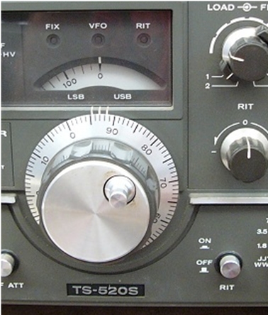
Rotate the large VFO knob until you hear a strong tone. Keep rotating until the tone gets lower and lower then stops. That is the Zero Beat point. Now, while holding the large knob firm, rotate the silver 100KHz dial behind the knob until the centre pointer rests on the nearest multiple of 25 (0, 25, 50, 75 etc)
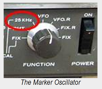
Place the FUNCTION knob back to the VFO position. This means that right now, for this band, the dial is reading the correct frequency and you are ready to go.
Note that if you were to switch to the opposite sideband, you would be exactly 3KHz out, as 3KHz is the bandwidth of an SSB transmission.
To be accurate, you need to re-do this task every time you select a different band. After just a few tries, becomes a short task that you do almost without thinking about it.
The Marker tone can also be used as a rough way to get the DRIVE knob near the correct tune point. Just rotate the DRIVE knob until the 25KHz marker tone is at its loudest.
If you wish to adjust the receive frequency a little without changing your transmit frequency, you can use the clarifier control knob, except note that on Kenwood radios they call the feature RIT for Receiver Incremental Tuning. Pushing the RIT button IN will arm the RIT knob and the receiver frequency can be trimmed above and below the transmit frequency.
5. SAVING & RECALLING MEMORY FREQUENCIES
There are none on this rig. It is possible to insert up to four fixed crystals to create four fixed ‘channels’ but this is rarely done.
6 SETTING REPEATER OFFSETS
No repeater offsets to worry about on this one
7. SETTING SUBAUDIBLE TONES (CTCSS)
No sub-audible tones to set either…
8. ADJUSTING POWER OUTPUT
There is a knob around the outside of the microphone sensitivity knob that will adjust transmitter power labelled CAR for CARRIER. Rotating this knob anti-clockwise will reduce the transmitter output, but this is not set to an absolute value, but just provides a a general reduction. To know what the output power is, an external wattmeter in line with the coax cable is still recommended. Be sure to re-tune the output stage if the output carrier level is significantly changed.
SPECIAL COMMENTS (HOW TO TUNE UP THE TRANSMITTER)
Tuning up the transmitter is an important process that must be done whenever you change bands, or move up or down a significant amount within the present band. Generally, the aim is to achieve the maximum output power for the lowest possible plate current. This is the point where the radio is at its most efficient and the transmission quality is at its cleanest. It is an essential part of owning a radio with vacuum tube final stages.
Prior to attempting a tune up ensure that the H.SW switch is in the Up position in order to put power on the vacuum tube filaments. Then give the radio about 1.5 to 2 minutes to warm up.
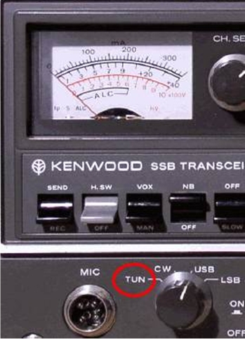
- Place the MODE switch in the USB or LSB position for a moment and rotate the DRIVE knob for maximum receiver noise.
- Place the PLATE knob that roughly corresponds with the band you wish to use.
- Set the CARRIER knob at the back of the MIC gain to about the 12 O’clock position. This will allow a preliminary tune to take place at a lower power setting.
- Set the LOAD knob to approximately halfway. The LOAD knob is an output impedance matching stage allowing the rig to match to an antenna impedance anywhere between 50 and 75 ohms.
- Set the METER switch to the position marker IP for Plate Current viewing. Then turn the MODE switch to the TUNE position. We are now ready to transmit.
- Flip the TX/RX switch up unto the SEND position and rotate the DRIVE knob again for a peak reading on your panel meter. If the meter reads too high, say greater than 2/3rds deflection then back the carrier level off a bit with the CARRIER control knob
When performing initial tune-ups, limit the transmit time to 10-15 second bursts.
- While transmitting, rotate the PLATE knob and look for s DIP in the meter movement. This will be the point of maximum efficiency.
- Turn the METER SWITCH to the RF position to show relative transmitted power. Then tweak the DRIVE and LOAD knobs again for a maximum reading on the meter.
- You can now restore the SEND switch to the Receive position and rotate the MODE switch to USB or LSB as required for the present band.
The radio is now tuned to about 95% of optimum and will be fine for normal operation. If you want to make prolonged transmissions at higher power levels, then increase the Carrier level to a higher setting and re-tune. (Steps e. through to i. )
Another feature worthy of mention is its Speech Processor. If you are working with a weak SSB station then pull out the MIC button to engage the internal speech processor, which will increase the average transmitted power.
They are an older set but they are still capable of transmitting solid signals that most solid state rigs are still jealous of today. If you find one in good condition, then hang onto it!
The TS520S IN MOVIES
The Japanese Anime movie titled Your Name shows a scene where a character visits a Ham friend and in the background we can see a familiar radio

Download this document as a PDF
 This Is Amateur Radio