P36
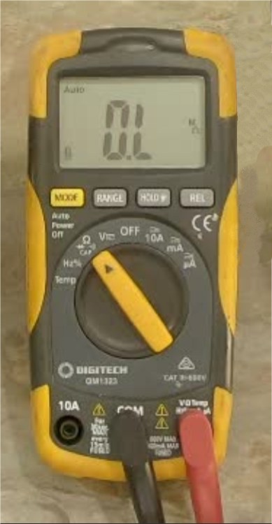
Using a Digital Multimeter
Using a Multimeter for measuring Voltage, Current, Resistance, continuity and other values
At the Foundation Qualification level, there is no requirement to use a multimeter, other than the need for checking continuity of an antenna cable. In practice all operators should be able to use a digital multimeter for basic measurements to check the condition of a battery, polarity of a power supply or to ensure that no dangerous voltages are present on an item of hardware.
With this page we shall describe some multimeter basics and provide useful links to locations of further reading.
Measuring a DC Voltage
Measuring DC is a fundamental use of a multimeter. First ensure that the probes are plugged into in the correct sockets, usually labelled COM and VOLTS. Then the leads can be applied to an unknown Direct Current voltage, such as a battery or a power pack to see what levels are like. Most meters have an AUTO RANGING feature which means that the meter will automatically adjust its own scale to match a small measurement of 1 or 2 volts, or hundreds of volts.
Measuring an AC Voltage
If an AC voltage is being measured, such as the secondary voltage of a power transformer, the process is the same as with measuring DC, except the user must first press the AC button on the meter. If an attempt is made to measure AC from a DC range, the meter will measure the average value of an AC signal, which will be zero. This can mislead the user to believe that there is no voltage present, even though a large AC voltage could be present at the probes.
Note that when using a multimeter to measure an AC potential, that it is showing the RMS (Root Mean Square) value of the AC. To read the Peak reading of the AC, simply multiply the displayed RMS reading by 1.414.
Measuring current flow (Amps)
Unless the digital meter has a dedicated ‘Clamp Meter’ function, the only way to measure current is to shift the positive lead of the meter to the socket labelled AMPS, then place the meter IN SERIES with the load, so that the current that is flowing through the meter is the same as the current flowing through the load.
Be wary that there is usually a fuse in-line with the AMPS terminal of your meter. If more current flows than the fuse rating, the fuse will blow and measurements will fail. Also note that if the meter is accidentally left in the AMPS range and the probes are connected across the terminals of a battery or power supply, the meter will be shorting out the supply and the meter fuse will immediately blow.
Measuring resistance (Ohms)
Most digital meters will have an OHMS range which lets the meter measure the resistance in ohms of a passive item, such as a resistor or wire. Ensure that there is no power being applied to the resistance under test or the meter result will not be accurate. A digital meter can’t measure the integrity of a diode simply on the OHMS range, because the voltage across the probes is too low to activate semiconductor junctions. This is why most meters have a SELECT button which brings up a Diode symbol. In this position, the meter generates around 1.5 volts at the probes and diode & transistor junctions can be checked.
Measuring a semiconductor component
A diode or a transistor junction can be checked with a multimeter by switching to the Diode Test position. Often this is a selected option from the Ohms test position. It the negative probe is applied to the Bar end of a diode component (cathode) and the positive probe is applied to the opposite end (anode), then the meter should show the working voltage drop of that device. For most diodes this will be between 0.4 and 0.6 volts on the display. When the probes are reversed, there should be no reaction on the meter, no current flow. This is a sign that the diode junction is in good order. The same method may be used between the base and Emitter/collector of transistors, where a 0.6V reading of a transistor junction is common.
Note that with most meters, will not be capable of testing Light Emitting Diodes (LED’s), as LEDs usually require 2-3 volts across their connections to produce light and most meters do not produce more than 1.5V across the probes in the diode test mode. Unless the meter has a specific LED Test feature, it will not test the integrity of LED components.
Measuring continuity of a wire.
Most modern meters will have a Continuity Test position where the meter will beep when the two probes are shorted together. This can be used to check the integrity of of a coax patch cable. The continuity position is usually another sub function of the Ohms range of a digital multimeter.
A You Tube video on testing coax connectors may be viewed above or by following this link:
https://www.youtube.com/watch?v=d3N1A477ArQ
Measuring a frequency
Many multi meters have a dedicated feature for measuring frequency in Hertz, although this is not a particularly sensitive measurement. Most will not measure a frequency much higher than audio ranges. Simply place the meter selection switch in the Hz position and place the probes across a signal source. A value of Hertz or Kilohertz should be displayed.
The Foundation Level Study Guide has a section on using a multimeter for checking continuity.
The Foundation Level Study Guide
All Blue Tiles form part of the syllabus for the Foundation Level Recognition Certificate (operator licence). A primary source of information for many of the blue tile topics can be found within the Foundation Level Study Guide. This is a free download available at:
https://vkradioamateurs.org/flsg/ This is a digital book and contains many links to other resources and explanatory videos.

Information about checking the integrity of coax connectors relevant to Foundation Level Qualifications can be found in this book from Chapter 5, on Page 41.
There are many You Tube videos which describe how meters can be used. An excellent one may be viewed at this site: https://www.youtube.com/watch?v=0loXukB302Q
ACMA Syllabus Extract
According to the ACMA Foundation Syllabus, the required knowledge on this topic is:
5.3 Testing of Transmission Lines
Understand the reason for continuity and insulation testing a co-axial cable terminated with co-axial connectors.
Recall the continuity and insulation testing procedure.
