P45
Measuring AC & DC Circuits
Before measurements of any circuit are taken it is useful to know a little about what to expect in advance of the test.
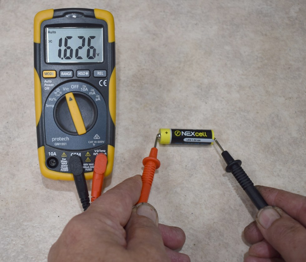
DC measurements are quite straightforward to perform. Set a multimeter to the DC Volts range and attach the two probes to a AA battery and most meters will automatically select the most appropriate range and reveal the battery voltage. A good cell should read around 1.5 to 1.6 volts.
If the probes were reversed and the red lead was applied to the negative end of the cell, a ‘minus’ sign would appear in front of the displayed value.
When measuring AC or Alternating Current there is a bit more to it.
Consider the circuit below where a battery is connected to a light via a two-pole toggle switch which has been wired to reverse the polarity of the battery to the lamp. The lamp would always be illuminated, only the polarity changes when the switch is activated or released.
If we leave the switch in one position, we are feeding the light with Direct Current (DC) and the lamp remains on. If we flip the switch back and forth rapidly at say ten times a second, as far as your eyes are concerned, the lamp keeps glowing at full brightness, but we are now feeding it with Alternating Current (AC) at 10 Hz.

The switch circuit here is a simple arrangement, producing what is known as a ‘Square Wave’. Regardless of the switch’s position, power is still being delivered; only the polarity is changing. The graph to the right shows this effect over time.
The voltage waveform on domestic power outlets also alternates between positive and negative in a similar manner, however the transition between positive and negative is more gradual, consisting of a wave-like shape known as a Sine Wave.
This Sine Wave frequency is also known as its Oscillation frequency.

The AC supply in a power outlet has a frequency of 50 Hz, which means each cycle takes only one-fiftieth of a second to complete.
One fiftieth of a second is equal to twenty milliseconds, so one full cycle is happening every 20 milliseconds.
PEAK versus RMS
This is where it gets interesting. There are moments in time where the waveform is at its peak and this is called the PEAK value. There are moments in time where the voltage passes through the zero-volts line where there is no voltage present at all.
Whenever AC is measured by a multimeter a different scale is used. This is called the RMS (Root Mean Square) value. On a clean waveform the RMS reading is always 70.7% of the PEAK value.
In an Australian power outlet like the one shown above, the outlet voltage is typically 230V to 240V AC. This is also an RMS value.
With a sine wave the voltage keeps varying in intensity. This means that if the voltage is applied to a load, say a heating coil, the heating effect will always be a bit lower than if it were a steady voltage at the PEAK value.
Another way to define the RMS voltage is that it has the same heating affect upon a load as the equivalent DC.
This is easier to understand with an example. Picture an AC sine wave with a PEAK value of say 100Volts. We apply this voltage to a heating coil which gets hot. The RMS voltage would be 70.7% of the peak voltage. Therefore if we put multimeter probes across the heater and set the meter to AC VOLTS range, the meter will only read 70.7V and not 100V.
Furthermore if we put together several batteries in series until we measured 70.7 Volts of DC, then applied it to the same heater, it would reach exactly the same temperature as the measured 70.7 V of AC we applied earlier.
It is important to understand the difference between the PEAK and RMS values, because some electronic components such as capacitors and transistors have maximum safe working voltages. These parts would still be exposed to the instantaneous PEAK values of AC and should be chosen to withstand the PEAK and not the RMS value.
The Foundation Level Study Guide
All Blue Tiles form part of the syllabus for the Foundation Level Recognition Certificate (operator licence). A primary source of information for many of the blue tile topics can be found within the Foundation Level Study Guide. This is a free download available at:
https://vkradioamateurs.org/flsg/ This is a digital book and contains many links to other resources and explanatory videos.

Information on AC and DC measurement can be found from Chapter 3 on Pages 15 to 19 in this book
ACMA Syllabus Extract
According to the ACMA Foundation Syllabus, the required knowledge on this topic is:
3.9 The Sine Wave
Recall the graphic representation of a sine wave and that sine waves are produced by oscillators.
3.10 Mains Electricity Supply
Recall the voltage and frequency of the mains electricity supply used in Australia.
