P55
Transmitter & Receiver Diagrams
In electronics, we often use simplified circuit diagrams in a format that looks like a flow chart, using boxes with the name of the circuit and lines to explain the operation of equipment. These are called Block Diagrams.
Below is the block diagram of a simple Continuous Wave (CW) transmitter capable of transmitting a short distance.
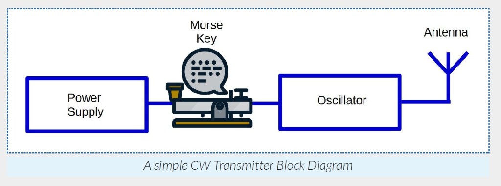
The next evolutionary step is to transmit the human voice by removing the Morse
key and adding some additional circuits to our transmitter block diagram.
For voice signals to be intelligible, they need to be at least telephone quality. This
requires audio frequencies between 300Hz to 3000Hz to be transmitted. To do
this, we need to combine the voice from the microphone with the Radio Frequency
(RF) carrier produced by the oscillator to produce a modulated RF output.
This method of voice transmission is known as Radio Telephony.
Below is the block diagram of a simple Amplitude Modulation (AM) transmitter:
Receivers
We need to understand how a receiver can select the wanted transmission out of the many different radio signals an antenna receives.
The receiver example here is known as Tuned Radio Frequency (TRF) Receiver.
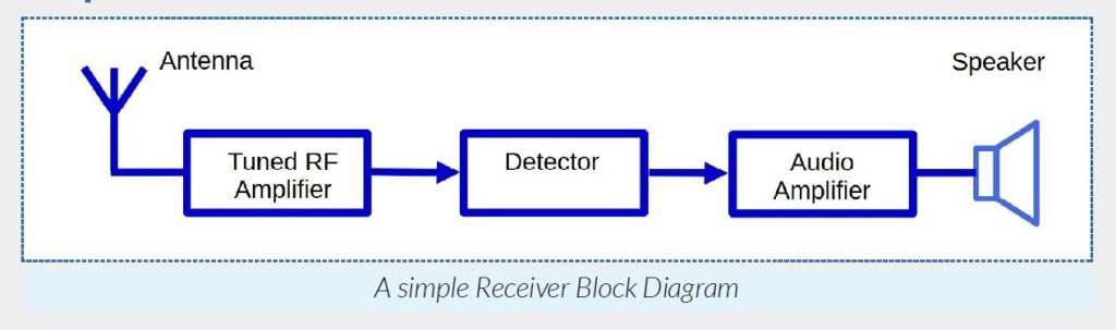
These are the stages that make up this basic receiver.
- Antenna. Captures electromagnetic radio waves on many frequencies and converts them into signals for processing by the receiver.
- Tuned RF Amplifier. Really two blocks in one. The first block is a tuned circuit, which is a type of filter that selects the specific frequency you want to receive.
- The narrower or sharper this filter, the better the selectivity (i.e. the better you can ignore all other frequencies and “zoom in” on the frequency you want to receive).
- The second is a Radio Frequency Amplifier which improves receiver sensitivity and makes the signal stronger for the next stage. This amplifier is also designed to introduce as little additional noise as possible.
- Detector. Combines (mixes) the carrier with the sidebands to reproduce the microphone audio from the transmitter.
- The carrier is filtered out and only the audio is passed on to the next stage.
- Audio Amplifier. Amplifies the audio signal output from the detector sufficiently to drive headphones and/or a loudspeaker. Includes a potentiometer (volume control) to adjust the volume level.
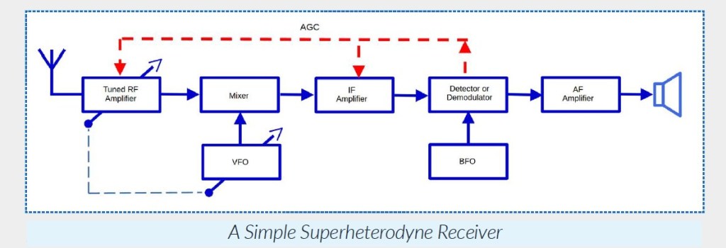
The TRF Receiver has limitations on its selectivity and sensitivity. Improved sensitivity, selectivity and stability are generally found in designs such as the Superheterodyne Receiver (shown below) and in modern Software-defined Radio (SDR).
More detail on this topic is in the Foundation License Study Guide
The Foundation Level Study Guide
All Blue Tiles form part of the syllabus for the Foundation Level Recognition Certificate (operator licence). A primary source of information for many of the blue tile topics can be found within the Foundation Level Study Guide. This is a free download available at:
https://vkradioamateurs.org/flsg/ This is a digital book and contains many links to other resources and explanatory videos.
Information about basic Transmitter & Receiver diagrams relevant to Foundation Level Qualifications can be found in this book from Chapter 4, on Pages 24 to 30
ACMA Syllabus Extract
According to the ACMA Foundation Syllabus, the required knowledge on this topic is:
4.1 Block or Concept diagrams of simple Transmitters and Receivers
Identify, using supplied block diagrams, the names of the stages in a simple transmitter and receiver.
