P60
Need for Antenna Matching
Antenna matching is important
There are two main requirements of any antenna that has been connected to a transmitter.
- The antenna has to be resonant at the transmitter frequency
- It must have an impedance that matches the transmitter impedance.
If those two conditions are met, then the transmitter should be able to transmit energy through that antenna. This does not take into consideration the efficiency of the antenna, how far above the ground it is, or whether it is pointing in the right direction.
Resonance
This is a large topic but essentially an antenna must be tuned to a frequency that matches the frequency of the transmitter. The physical length of the antenna controls its resonant frequency, so the length of the antenna may have to be adjusted for correct operation.
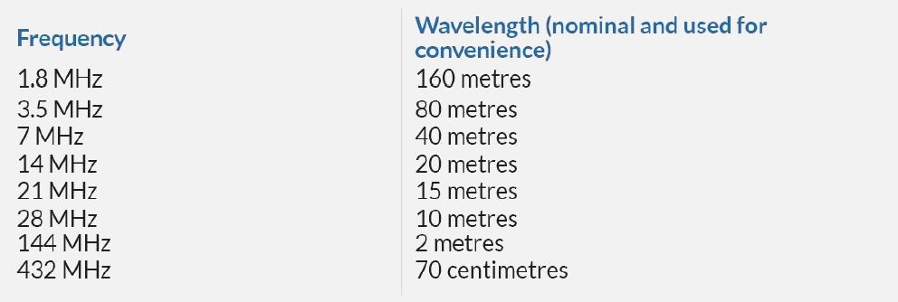
For example, on the 28 MHz band a full wavelength is 10 Metres. Therefore a half-wavelength dipole for that band is going to be approximately 5 metres long. The table below shows an approximation of Amateur frequencies and nominal wavelength.
There are websites with on-line calculators which provide accurate dimensions for achieving antenna resonance.
https://www.omnicalculator.com/physics/dipole
Impedance
This is another large topic, but the basics are straightforward. The three key parts of a station each have a characteristic impedance. This is a value measured in ohms. The impedance of the radio at the antenna socket is 50 ohms. The impedance of a functioning antenna designed for coaxial cable will be close to 50 ohms. The coax cable itself will have a working impedance of 50 ohms.
If all three parts are connected together and each is close to 50 ohms, then there will be a good impedance match and little, if any, power will be reflected back to the transmitter. All the transmitter energy will be radiated successfully.
This Reflected energy is called Voltage Standing Wave Ratio (VSWR) and we want this reflected power to be minimal.
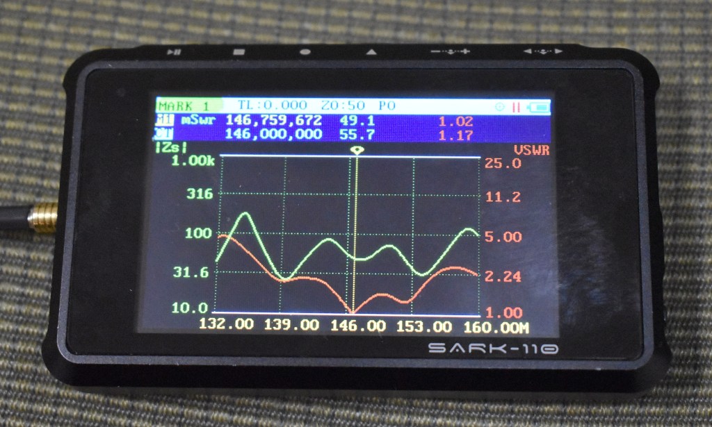
The image below shows a small Antenna Analyser testing a well matched vertical antenna on the 2 metre. There vertical yellow line represents the target frequency of 146.7 MHz. There are two curved lines. The green trace shows the impedance. On the target frequency, this is 49.1 Ohms, close to the ideal 50 Ohms. The red trace shows VSWR or Reflected Power. The trace dips close to zero reflected power at the target frequency. This is also ideal. The red trace is effectively showing where the antenna is resonant.
Where the readings on the Analyser are showing a good match, the transmitter can be connected directly to the antenna.
If the match is not good, either the antenna requires adjustment, or an Antenna Tuning Unit (ATU) should be used. Providing the impedance mismatch between the antenna and the feedline is not too great, an Antenna Tuning Unit can compensate and make the antenna usable. Some Antenna Tuning Units are separate items of equipment that are placed in-line with the antenna cable. Many modern HF transceivers have automatic antenna tuners built into the radio and are activated at the press of a button. VHF and UHF radios generally require the antenna itself to be correctly matched.
More information on Antenna Tuning Units can be found on this page:
https://thisisamateurradio.com/p63-using-antenna-tuners/
More detail about VSWR measurements can be found on this page:
https://thisisamateurradio.com/p62-introducing-vswr-principles/
The Foundation Level Study Guide
All Blue Tiles form part of the syllabus for the Foundation Level Recognition Certificate (operator licence). A primary source of information for many of the blue tile topics can be found within the Foundation Level Study Guide. This is a free download available at:
https://vkradioamateurs.org/flsg/ This is a digital book and contains many links to other resources and explanatory videos.
Information about antenna matching relevant to Foundation Level Qualifications can be found in this book from Chapter 5, on Pages 33 to 35
ACMA Syllabus Extract
According to the ACMA Foundation Syllabus, the required knowledge on this topic is:
5.11 Antenna Matching
Recall the need to match an antenna to a transmission line and to minimise the Voltage Standing Wave Ratio (VSWR).
5.12 Antenna Tuning Unit
Recall the uses, purposes and adjustment of a typical manual ATU.
5.13 Baluns
Recall that when feeding a balanced antenna with an unbalanced transmission line (co-axial cable), the preferred practice is to use a balun.
5.14 Voltage Standing Wave Ratio (VSWR)
Recall the correct placement, use and adjustment of an VSWR meter.
5.15 Acceptable VSWR
Recall that when testing a transmitter, a non-radiating load (dummy load) is commonly used to prevent a signal from being radiated.
