P62
VSWR Principles
Whenever the impedances are not equal, some of the RF power generated by the transmitter ‘bounces back’ from the antenna and gets reflected back along the transmission line towards the transmitter (which means the antenna can’t radiate it). These reflections interfere with the RF power that’s travelling forwards, causing Voltage Standing Waves to appear along the transmission line.
Standing Waves are undesirable, but they are actually also very useful because they are easy to measure and can be used to indicate how near or how far the antenna is from resonance and how well the impedances are matched.
A Standing Wave Meter (SWR Meter) is a very useful piece of test equipment for measuring the ratio of transmitted and reflected power.
Periodically check your antennas
It should be noted that when operating a transmitter into an antenna with a high SWR, that the reflected power can cause interference to nearby receivers and other electronic equipment. Therefore a station operator should periodically check the integrity of their antenna to ensure that the SWR is at an acceptably low value.
This video clip describes the process of using an SWR meter to measure the quality of antenna matching.
Antenna is too short or too long?
While an SWR meter on a radio displays reflected power when an antenna is not resonant, a high SWR reading does not immediately tell the operator if the antenna resonance is above or below the present frequency. This makes it difficult to determine if the antenna is currently too long or too short?
There is a method to resolve this question. If an SWR check is performed at the Low end of a given band and is checked again at the High end of the band, one figure is usually slightly better than the other.
- If the SWR was slightly better at the top of the allocation, then the antenna is too short and should be lengthened before trying again.
- If the SWR was slightly better at the low end of the frequency allocation, then the antenna is too long and should be trimmed.
This process should be repeated until the best SWR figure is in the centre of the band in use.
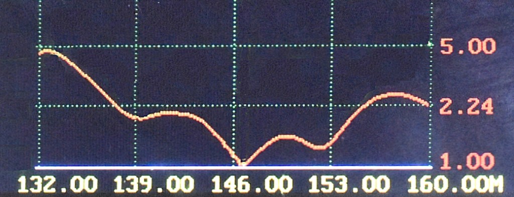
For example, the 2 Metre band is from 144 to 148 MHz. Usually antennas are tuned to resonance between 146 to 146.5 MHz.
The red line on this SWR plot shows that the resonant frequency (lowest SWR reading) is a good match near the centre of the 2 metre band.
Balanced vs Unbalanced antennas
Coax cables are ‘unbalanced’ feedlines as there is an active centre conductor and the braid or shield layer remains close to ground potential. However many antenna types, such as the simple dipole are ‘Balanced’ which means that that they are symmetrical and input terminals are not bonded to ground.
A coax cable should not be connected directly to a dipole without some form of Balanced-to-Unbalanced matching transformer, called a Balun. Without this transformer coupling in place, the feedline may become an active part of the antenna and this can introduce unwanted noise.
The operation and selection of Baluns are detailed on a separate page:
https://thisisamateurradio.com/p71-antenna-matching-with-a-balun/
The Foundation Level Study Guide
All Blue Tiles form part of the syllabus for the Foundation Level Recognition Certificate (operator licence). A primary source of information for many of the blue tile topics can be found within the Foundation Level Study Guide. This is a free download available at:
https://vkradioamateurs.org/flsg/ This is a digital book and contains many links to other resources and explanatory videos.
Information about VSWR relevant to Foundation Level Qualifications can be found in this book from Chapter 5, on Pages 33 to 35
ACMA Syllabus Extract
According to the ACMA Foundation Syllabus, the required knowledge on this topic is:
5.11 Antenna Matching
Recall the need to match an antenna to a transmission line and to minimise the Voltage Standing Wave Ratio (VSWR).
5.12 Antenna Tuning Unit
Recall the uses, purposes and adjustment of a typical manual ATU.
5.13 Baluns
Recall that when feeding a balanced antenna with an unbalanced transmission line (co-axial cable), the preferred practice is to use a balun.
5.14 Voltage Standing Wave Ratio (VSWR)
Recall the correct placement, use and adjustment of an VSWR meter.
5.15 Acceptable VSWR
Recall that when testing a transmitter, a non-radiating load (dummy load) is commonly used to prevent a signal from being radiated.
