P77
RF Resonance Principles
The term Resonance is widely used in radio topics, but is often not understood. Partially because it can be expressed several ways. Here we shall return to some basics.
The component called a ‘Resistor’ gets its title because it has a fixed resistance measured in ohms, regardless of what circuit it is in or what frequencies are passing through it.
Capacitors and inductors are different. They are reactive components that also have resistance in Ohms, but that resistance varies with the frequency which is passing through the component.
Resistance in ohms of a capacitor is called Capacitive Reactance and its symbol is XC. Its resistance will fall as the frequency passing through it increases.
In an inductor, the effect is similar, but mirrored. As the applied frequency increases its Inductive Reactance, XL increases.
This effect can be seen in the diagram below.

These effects are more than an academic exercise. Consider a Tone or Treble control on an audio amplifier which increases the high frequencies we hear through a speaker. When we turn the knob we using a variable resistor to gradually engage or disengage a capacitor across the audio. The capacitor tends to short out the higher frequencies and allows the lower frequencies to reach the speaker.
The same effect happens when you place a resistor and capacitor in parallel and place it across an antenna. There is an XC curve and an XL curve. One blocks the high frequencies, one blocks the lower frequencies and the signal that is most likely to get through for listening is where the two curve lines intersect.
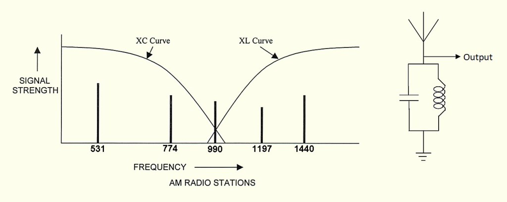
By putting a Capacitor and an Inductor together we have created a Tuned Circuit. Where the two resistance curves cross, which is when the XC value and the XL values are the same, this is called the point of Resonance.
In the above diagram, the two lines intersect over the AM broadcast frequency of 990 KHz. (The Albury/Wodonga station) The frequencies above and below this station will be shorted to earth and only the 990 KHz frequency will be extended through to our speakers via a Detector and Audio Amplifier stage. This is the basis of a simple TRF receiver.
Any time we place an inductor and capacitor together, a Tuned Circuit is formed. It will always be resonant somewhere.
We can calculate the resonant frequency of any capacitor and inductor combination using this formula:

In Amateur exams, candidates should be able to recognise what this formula represents, but would not be called upon to perform calculations with it
The Foundation Level Study Guide
All Blue Tiles form part of the syllabus for the Foundation Level Recognition Certificate (operator licence). A primary source of information for many of the blue tile topics can be found within the Foundation Level Study Guide. This is a free download available at:
https://vkradioamateurs.org/flsg/ This is a digital book and contains many links to other resources and explanatory videos.
Information on Transmitters and Receivers utilising this principle of Resonance may be found on Chapter 4 in this book
