The Australian Amateur Band Plan
WRC Abbreviations
Making sense of ACMA spectrum abbreviations
When reviewing ACMA documents that contain frequencies and permissible modulation methods, you will encounter codes like J3E and C3F instead of common references such as SSB, AM, FM. The ACMA have adopted the conventions described in a World Radio Conference (WRC) Appendix document and provide a link to it as an explanation. The original WRC document can be viewed HERE, but an extract if this document has been provided below.
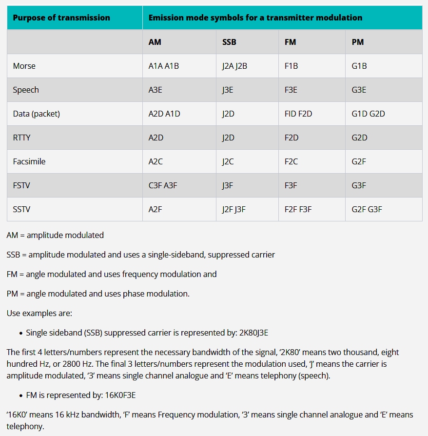
Some common Transmission Modes
The document is complex because it encompasses all conceivable transmission modes. However the bulk of Amateur transmissions take place using relatively few modes. For clarity, here are some common transmission modes and their abbreviated terms, as sourced from the ACMA website:
Understanding Transmitter Power Levels
ACMA documents use abbreviations to refer to permissible transmitted power levels for each class of operator. These are usually expressed as a value of pX and pY, which can be confusing when first encountered. Here are the common definitions of these abbreviations:
- pX means Peak Envelope Power (PEP): This is the average power supplied to an antenna transmission line by a transmitter during one radio frequency (RF) cycle at the crest (highest point) of the modulation envelope under normal operating conditions.
- pY means Mean Power: This is the average power supplied by a transmitter over a time period that is sufficiently long compared with the lowest frequency encountered in the modulation.
These different definitions allow for appropriate power measurement methods depending on the type of modulation used:
- For constant level carriers (like CW/Morse code, unmodulated AM, or FM), the mean power (pY) is used.
- For variable level carriers (like Single Sideband/SSB modulation), which only produce power when modulated, the peak envelope power (pX) is the relevant measure.
Unless otherwise stated in the LCD for specific parts of the spectrum, these are the usual maximum permissible power levels for Australian Amateurs
- Foundation Operators: 10 watts pX peak for all transmission modes
- Standard Operators: 100 watts pX (SSB), 30 watts pY (AM/FM/CW)
- Advanced Operators: 400 watts pX (SSB), 120 watts pY (AM/FM/CW)
APPENDIX 1 (REV.WRC-12)
Classification of emissions and necessary bandwidths
Section 1 – Necessary bandwidth
1..2.1 The necessary bandwidth, as defined in No. 1.152 and determined in accordance with the formulae and examples, shall be expressed by three numerals and one letter. The letter occupies the position of the decimal point and represents the unit of bandwidth. The first character shall be neither zero nor K, M or G.
1.2.2 Necessary bandwidths:
between 0.001 and 999 Hz shall be expressed in Hz (letter H);
between 1.00 and 999 kHz shall be expressed in kHz (letter K);
between 1.00 and 999 MHz shall be expressed in MHz (letter M);
between 1.00 and 999 GHz shall be expressed in GHz (letter G).
1.2.3 For the full designation of an emission, the necessary bandwidth, indicated in four characters, shall be added just before the classification symbols. When used, the necessary bandwidth shall be determined by one of the following methods:
Examples:
0.002 Hz = H002 6 kHz = 6K00 1.25 MHz = 1M25
0.1 Hz = H100 12.5 kHz = 12K5 2 MHz = 2M00
25.3 Hz = 25H3 180.4 kHz = 180K 10 MHz = 10M0
400 Hz = 400H 180.5 kHz = 181K 202 MHz = 202M
2.4 kHz = 2K40 180.7 kHz = 181K 5.65 GHz = 5G65
Section 2 – Classification
2.3 The class of emission is a set of characteristics conforming to 2.4 below.
2.4 Emissions shall be classified and symbolised according to their basic characteristics as given in Sub-Section 2A and any optional additional characteristics as provided for in Sub-Section 2B.
2.5 The basic characteristics are:
1) First symbol – type of modulation of the main carrier;
2) Second symbol – nature of signal(s) modulating the main carrier;
3) Third symbol – type of information to be transmitted.
Modulation used only for short periods and for incidental purposes (such as, in many cases, for identification or calling) may be ignored provided that the necessary bandwidth as indicated is not thereby increased.
Sub-Section 2A – Basic characteristics
2.6 1) First symbol – Type of modulation of the main carrier
1.1) Emission of an unmodulated carrier N
1.2) Emission in which the main carrier is amplitude-modulated (including cases where sub-carriers are angle-modulated)
1.2.1) Double-sideband A
1.2.2) Single-sideband, full carrier H
1.2.3) Single-sideband, reduced or variable level carrier R
1.2.4) Single-sideband, suppressed carrier J
1.2.5) Independent sidebands B
1.2.6) Vestigial sideband C
1.3) Emission in which the main carrier is angle-modulated
1.3.1) Frequency modulation F
1.3.2) Phase modulation G
1.4) Emission in which the main carrier is amplitude-and angle-modulated either simultaneously or in a pre-established sequence D
1.5) Emission of pulses
1.5.1) Sequence of unmodulated pulses P
1.5.2) A sequence of pulses
1.5.2.1) Modulated in amplitude K
1.5.2.2) Modulated in width/duration L
1.5.2.3) Modulated in position/phase M
1.5.2.4) in which the carrier is angle-modulated during the angle-period of the pulse Q
1.5.2.5) which is a combination of the foregoing or is produced by other means V
1.6) Cases not covered above, in which an emission consists of the main carrier modulated, either simultaneously or in a pre-established sequence, in a combination of two or more of the following modes: amplitude, angle, pulse W
1.7) Cases not otherwise covered X
2) Second symbol – Nature of signal(s) modulating the main carrier
2.1) No modulating signal 0
2.2) A single channel containing quantised or digital information without the use of a modulating sub-carrier. 1
2.3) A single channel containing quantised or digital information with the use of a modulating sub-carrier. 2
2.4) A single channel containing analogue information . 3
2.5) Two or more channels containing quantised or digital information. 7
2.6) Two or more channels containing analogue information. 8
2.7) Composite system with one or more channels containing quantised or digital information, together with one or more channels containing analogue information. 9
2.8) Cases not otherwise covered X
3) Third symbol – Type of information to be transmitted
3.1) No information transmitted N
3.2) Telegraphy – for aural reception A
3.3) Telegraphy – for automatic reception. B
3.4) Facsimile C
3.5) Data transmission, telemetry, telecommand D
3.6) Telephony (including sound broadcasting) E
3.7) Television (video) F
3.8) Combination of the above W
3.9) Cases not otherwise covered X
Sub-Section 2B – Optional characteristics for the classification of emissions
Two optional characteristics should be added for a more complete description of an emission. These are:
Fourth symbol – Details of signal(s)
Fifth symbol – Nature of multiplexing
Where the fourth or fifth symbol is used it shall be as indicated below.
Where the fourth or the fifth symbol is not used this should be indicated by a dash where each symbol would otherwise appear.
1) Fourth symbol – Details of signal(s)
1.1) Two-condition code with elements of differing numbers and/or durations A
1.2) Two-condition code with elements of the same number and duration without error-correction B
1.3) Two-condition code with elements of the same number and duration with error-correction C
1.4) Four-condition code in which each condition represents a signal element (or one or more bits) D
1.5) Multi-condition code in which each condition represents a signal element (of one or more bits) E
1.6) Multi-condition code in which each condition or combination of conditions represents a character F
1.7) Sound of broadcasting quality (monophonic) G
1.8) Sound of broadcasting quality (stereophonic or quadraphonic) H
1.9) Sound of commercial quality (excluding categories given in 1.10) and 1.11)) J
1.10) Sound of commercial quality with the use of frequency inversion or band-splitting K
1.11) Sound of commercial quality with separate frequency-modulated signals to control the level of demodulated signal L
1.12) Monochrome M
1.13) Colour N
1.14) Combination of the above W
1.15) Cases not otherwise covered X
2) Fifth symbol – Nature of multiplexing
2.1) None N
2.2) Code-division multiplex C
2.3) Frequency-division multiplex F
2.4) Time-division multiplex T
2.5) Combination of frequency-division multiplex and time-division multiplex W
2.6) Other types of multiplexing X
